
User Guide

21
103876-08 - 1/19
CL
Installation & Service Manual
away from the inlet so that the regulator is not
subjected to excess temperatures that may
occur during “off” periods when it is possible
for heat to be conducted back through the
supply line. The flow regulator also limits
the flow of supply water regardless of inlet
pressure variations in the range of 20 to 125
psi.
2. Tempering Hot Water — Installation of an
automatic mixing valve will lengthen the
delivery of the available hot water by mixing
some cold water with the hot. This prevents
excessive and possibly scalding hot water
at the fixtures. In addition, savings of hot
water will be achieved since the user will not
waste as much hot water while seeking water
temperature to his liking. Higher temperature
hot water required by dishwashers and
automatic washers is possible by piping the
hot water from the heater prior to entering
the mixing valve. The mixing valve should be
“trapped” by installing it below the cold water
inlet to heater to prevent lime formation in the
valve.
WARNING
Install automatic mixing
valve at tankless heater outlet to avoid risk of
burns or scalding due to excessively hot water
at fixtures. Adjust and maintain the mixing
valve in accordance with the manufacturer's
instructions.
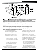
3. Flushing of Heater — All water contains some
sediment which settles on the inside of the
coil. Consequently, the heater should be
periodically backwashed. This is accomplished
by installing hose bibs as illustrated and
allowing water at city pressure to run into
hose bib A, through the heater, and out hose
bib B until the discharge is clear. The tees in
which the hose bibs are located should be the
same size as heater connections to minimize
pressure drop.
4. Hard Water — A water analysis is necessary
to determine the hardness of your potable
water. This is applicable to some city water
and particularly to well water. An appropriate
water softener should be installed based on
the analysis and dealer’s recommendation.
This is not only beneficial to the tankless heater
but to piping and fixtures plus the many other
benefits derived from soft water.
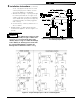
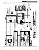
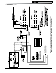
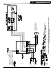
K. Indirect Water Heater Piping
1. Connect Indirect Water Heater Piping as
shown in Figures 12A and 12B for water boilers
and Figures 13 and 16 for steam boilers. Refer
to Indirect Water Heater Instruction Manual for
additional installation information.
a. CL Series Water Boiler - Figures 12A and
12B show indirect water heater piping on
typical hot water heating system. Boiler
piping is the same as for any two-zone
system. Figures 12A and 12B show
circulator zoning, which is usually preferred
for indirect water heaters. Size the
circulator and indirect water heater piping
to obtain the boiler water flow through
the indirect water heater called for by the
indirect water heater manufacturer. Refer to
the indirect water heater instruction manual
for additional details.
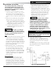
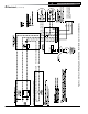
b. CL Series Steam Boiler - All CL Series
steam boilers are equipped with tappings
to permit the connect of an indirect water
heater, see Figures 2B and 16. In this type
of system, hot boiler water is drawn from
below the water line and passed through
the heat exchanger in the indirect water
heater.
This section describes boiler-side piping
only. Refer to the indirect water heater
instruction manual for additional details.
L. Chimney Venting
1. Chimney venting is an important part of a
safe and efficient oil fired appliance system.
Contact your local fire and building officials
on specific requirements for restrictions and
the installation of fuel oil burning equipment.
In addition, consult with a professional
knowledgeable on the requirements of NFPA
31 – Standard for the Installation of Oil-Burning
Equipment and NFPA 211 - Standard for
Chimneys, Fireplaces, Vents, and Solid Fuel-
Burning Appliances for installations in the
United States. Installations in Canada must be
reviewed with a professional knowledgeable
on the requirements of CSA B139 – Installation
Code for Oil-burning Equipment.
2. The safe venting of oil fired boilers is
dependant on many factors. Some of these
factors include:
a. sufficient draft during the entire heating
season to allow for the safe discharge of
combustion by-products and;
b. suitable corrosion protection in the event of
condensing flue gases. Only a trained and
qualified contractor may install this product.
3. The CL shall be vented into any of the
following:
a. Masonry or metal chimney. Build and install
in accordance with local buildings codes;
3 Installation Instructions (continued)