
User Guide

13
103876-08 - 1/19
CL
Installation & Service Manual
ii. Installation:
To insert drawer assembly, reverse the
procedure in Step i above.
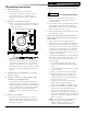
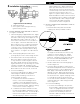
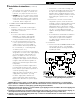
b. Nozzle Replacement, refer to Figure 6.
i. Remove the NOZZLE ADAPTER (2) from
the DRAWER ASSEMBLY by loosening
the SCREW (1).
ii. Remove existing nozzle from nozzle
adapter.
iii. Insert the proper NOZZLE into NOZZLE
ADAPTER and tighten securely (DO NOT
cover tighten), refer to Table 14B (at rear
of this manual).
iv. Replace adapter, with nozzle installed,
into drawer assembly and secure with
screw (1).
Figure 6: Riello Nozzle Replacement
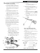
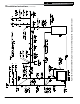
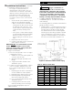
c. Inspect and measure burner electrodes.
Refer to Figure 7 for the proper electrode
settings.
d. Re-install Drawer Assembly into Combustion
Head per Step 3a above.
e. Insertion Depth, verify the distance between
the tip of the end cone is equal to the
distance specified in Table 14B (at rear of
this manual).
f. Turbulator Setting, refer to Figure 8.
g. Pump Connections and Port Identification,
refer to Figure 9.
This burner is shipped with the oil pump
Figure 7: Riello Electrode Setting
Instruction included with baffle.
h. Reinstall Beckett MB(L1) or MD(V1) Head.
i. Inspect and measure burner electrodes.
Refer to Figure 27 for the proper electrode
setting. Readjust electrode setting to the
proper dimensions if necessary. Refer to
Figure 27.
j. Reinstall nozzle line electrode assembly.
k. Connect copper connector tube.
l. Inspect Beckett head setting on left side
of burner by insuring the line on the label
MB(L1) or the blue line MD(V1) are aligned,
readjust if necessary. Refer to Figure 27.
m. Tighten knurled nut.
n. Swing igniter closed, rotate tabs and tighten
two (2) igniter screws.
3. On the Riello 40 Series Oil Burner, use
the following procedure to complete the
inspection, check the settings and to change
the nozzle to a lower firing rate: Refer also to
Model F3 & F5 Installation Manual, Riello 40
Series Residential Oil Burners (C6501010) or
Model F10 Installation Manual, Riello 40 Series
Residential Oil Burners No. 2902554.
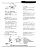
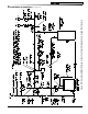
a. Installation/Removal of Drawer Assembly,
refer to Figure 5.
i. Removal:
• Disconnect oil delivery tube nut from
pump.
• Loosen SCREW (3), and then unplug
PRIMARY CONTROL (1) by carefully
pulling it back and then up.
• Remove the AIR TUBE COVER
PLATE (5) by loosening the retaining
SCREW (4) (Two SCREWS-Model F5).
• Loosen SCREW (2), and then slide
the complete drawer assembly out of
the combustion head as shown.
Figure 5: Installation/Removal of
Riello Drawer Assembly
3 Installation Instructions (continued)