
Install Instructions

19
103876-08 - 1/19
CL
Installation & Service Manual
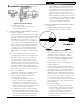
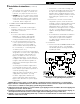
Note:
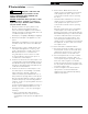
• The GeniSys 7505 Oil Primary Control has
pre-installed "T-T" jumper. To activate "T-T"
terminals, "T-T" jumper must be removed.
• DO NOT remove "T-T" jumper unless wiring
diagram indicates a direct connection from
thermostat and/or tankless heater aquastat
control to the oil burner primary control's "T-
T" terminal. Refer to Figure 23.
I. CONNECT SUPPLY AND RETURN PIPING TO
HEATING SYSTEM.
1. Clearances — Steam and hot water pipes
shall have clearances of at least ½” from all
combustible construction.
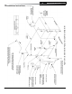
2. Water Boiler
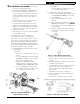
a. For Forced Circulation HOT WATER
HEATING. See Figures 12A and 12B.
Consult I=B=R, "Residential Hydronic
Heating Installation and Design Guide".
b. Use a boiler water bypass if the boiler
is to be operated in a system which has
a large volume or excessive radiation
where low boiler water temperature may
be encountered (i.e. converted gravity
circulation system, etc.).
Install a pipe tee in the boiler return piping
along with a second tee in the supply piping
as shown in Figures 12A and 12B. The
bypass should be the same size as the
supply and return lines. Locate valves in
the bypass and supply outlet as illustrated
in Figures 12A and 12B for regulation of
water flow to maintain higher boiler water
temperature.
Set the by-pass and boiler supply valves
to a half throttle position to start. Operate
boiler until the system water temperature is
a normal operating range.
Adjust the valves to provide 180° to 200°F
supply water temperature. Opening
the boiler supply valves will raise the
system temperature, while opening the
bypass valve will lower the system supply
temperature.
c. If this boiler is connected to heating coils
located in air handling units where they may
be exposed to refrigerated air the boiler
piping must be equipped with flow control
valves to prevent gravity circulation of boiler
water during the operation of the cooling
system.
d. If this boiler is used in connection with
refrigeration systems, the boiler must be
installed so that the chilled medium is piped
in parallel with the heating boiler using
appropriate valves to prevent the chilled
medium from entering the boiler, see Figure
14. Also, consult I=B=R, "Residential
Hydronic Heating Installation and Design
Guide".
e. A hot water boiler installed above radiation
level must be provided with a low water
cutoff device as part of the installation.
See Appendix A, Low Water Cut-Off for
additional details.
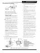
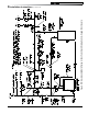
3. Steam Boiler
a. For Recommended STEAM BOILER PIPING
refer to Figure 13. Also, consult I=B=R,
"Residential Hydronic Heating Installation
and Design Guide".
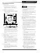
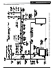
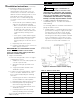
Figure 14: Recommended Piping for Combination
Heating & Cooling (Refrigeration) Systems
NOTICE Before using copper for steam piping, consider the following characteristics of copper piping:
1. High coefficient of thermal expansion can induce mechanical stresses and cause expansion/contraction
noises if not accounted for in the piping system design and installation,
2. High heat transfer rate (heat loss) of un-insulated copper piping must be included in the normal piping and
pickup factors used to size the boiler,
3. Soldering or brazing pastes and fluxes that end up in the system can cause poor heat transfer, surging, an
unsteady water line and wet steam if not thoroughly removed during boil out procedure and,
4. Galvanic corrosion of the adjoining metal may occur due to dissimilar metals in certain water chemistries if
dielectric unions are not used.
3 Installation Instructions (continued)