
Product Overview


56
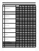
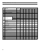
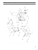
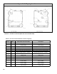
FIGURE A1: TAPPING LOCATIONS (SEE TEXT FOR TAPPING USES)
Table A1: Trim and Control Installation in Section Tappings
Tapping
Size
(NPT)
Steam Boiler with Probe LWCO
Steam Boiler with
Float LWCO
A 2 Supply Supply
B ½
Bush to ¼
Pressure Gauge
Bush to ¼
Pressure Gauge
C ½ Gauge Glass Nipple & Union Gauge, LWCO
D 2 Return Return
E ¾ 3" Nipple & Street Elbow Safety Relief Valve 3" Nipple & Street Elbow Safety Relief Valve
F 2 Bush to ¾ Drain Valve and/or Optional Return Bush to ¾ Drain Valve and/or Optional Return
G 2
Optional Supply (CGS30C - CGS60C)
Required Supply (CGS70C - CGS80C)
Optional Supply (CGS30C - CGS60C)
Required Supply (CGS70C - CGS80C)
H ¾
Bush to ¼ &
Syphon, Limit
Bush to ¼ &
Syphon, Limit
J ¾ Not Applicable Not Applicable
K ¾ Low Water Cutoff Plug
L 1 Surface Blow-Off Surface Blow-Off
M 1¼
Factory Plugged
Link SL™ Return
Factory Plugged
Link SL™ Return
N 1¼
Factory Plugged
Link SL™ Supply
Factory Plugged
Link SL™ Supply
P ¾
Factory Plugged
Link SL™ Limit
Factory Plugged
Link SL™ Limit
Appendix A - Tapping Locations