
Product Overview


22
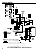
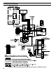
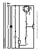
CGS-C Control System – Sequence of Operation
(Refer to Figures 16 & 17 for ladder and connection diagrams)
Sequence of Operation, Intermittent Ignition
1) When the boiler is energized, 24 volts is immediately applied to terminals “1” (blue) and “4” (yellow) on the vent
damper. Assuming that there is no call for heat, and that the damper switch is in the “automatic” position, the damper
will close. On boilers equipped with Hydrolevel CG400A probe type low water cut-offs, voltage is also always applied
to terminals “1” (blue) and “2” (yellow) on the low water cut-off to power the water level sensing circuit. On boilers
equippedwith#67oattypelowwatercut-offs,powerisalwaysappliedtoterminal“2”onthe#67LWCO.
2) Assuming that water is above the cut-off level, power will appear at terminal “3” on the CG400 LWCO or terminal “1”
on the #67 LWCO.
3) Assuming that steam pressure is below the pressure limit setting, power will appear on one side of relay contact 1R1
(Gray lead). Relay 1R is the R8225 mounted under the junction box.
4) Acallforheatfromthethermostatenergizesrelaycoil1Rcausingcontacts1R1tomake.Currentthenowsthrough
contacts 1R1 to pin terminal “2” (orange) at the vent damper and the damper opens.
5) Once the vent damper is fully open, an end switch inside the damper will make, energizing pin “3” (red) at the damper.
6) Currentpassesfromterminal“3”ontheventdamperthoughtheamerolloutandblockedvent(“spill”)switches.Under
normal conditions, both of these switches are made and voltage will therefore immediately appear across terminals
“24V” and “24V (GND)” on the ignition module.
7) Upon application of voltage across the “24V” and “24V (GND)” terminals, the ignition module will start an ignition
spark at the pilot and apply 24 volts across the pilot valve (terminals “PV” and “MV/PV”).
8) Oncethepilotisestablished,thepilotamewillactasadiode,convertingtheACcurrentattheelectrodetoahalfwave
DCcurrentatthepilot’sgroundstrap.ThisDCcurrentowsthroughtheboilertothe“GND(BURNER)”connectionon
theignitionmodule.Fortheignitionmoduletorecognizethatapilotameispresent,theDCcurrentowingintothis
terminal must be in excess of approximately 1.0 uA.
9) Oncetheignitionmoduledetectsthepresenceofapilotame,voltageisappliedacrossthemainvalve(terminals“MV”
and“MV/PV”),openingthevalveandestablishingmainame.
10) The way in which the ignition module handles failure to establish pilot or the loss of an already established pilot depends
upon the exact ignition module supplied with the boiler. For more information on module operation, consult the ignition
moduleinstructionssuppliedwiththeboilerorthelocalNewYorkerrepresentative.
Safety Control Operation - Intermittent Ignition
Hydrolevel CG400A Low Water Cut-off - Interrupts burner operation if the water in the boiler drops below a safe level. As the
water drops past the cut-off point, the amber lamp on the CG400 will glow. The CG400 will interrupt power to the burners 15 sec-
onds after the water level drops past the cut-off point. This feature prevents short cycling of the burners due to a bouncing water
line. The burners will then remain off until 30 seconds after the water level has been raised above the cut-off point.
TheCG400isalsoequippedwithafeaturewhichwillshutdowntheburnersaftertheyhavebeenringfor10minutes,
regardless of the water level status. The CG400 then keeps the burners off for 90 seconds, allowing the water level and any foam
which is present to settle. During this 90 second interval, the green LED on the CG400 will glow. If the water level is still above
the cut-off line at the end of this 90 second interval, the CG400 will restart the burners.
The vent damper will close when the low water cut-off interrupts burner operation.
X. Electrical (continued)