INSTALLATION, OPERATING AND SERVICE INSTRUCTIONS CGS-C™ Series GAS BOILER 9700609 BEFORE INSTALLATION: READ THIS MANUAL SAVE THESE INSTRUCTIONS Installing contractor and homeowner should read and be informed as to the proper installation and operation of this boiler. The manufacturer will not be responsible for improper installation or operation. This manual and all associated instruction material should be conspicuously posted near the boiler.
WARNINGS FOR THE HOMEOWNER FOLLOW ALL INSTRUCTIONS and warnings printed in this manual and posted on the boiler. INSPECT THE BOILER ANNUALLY. To keep your boiler safe and efficient, have a service technician follow the Service checklist near the end of this manual. IF YOU ARE NOT QUALIFIED to install or service boilers, do not install or service this one. THE BOILER MAY LEAK WATER at the end of its useful life. Be sure to protect walls, carpets, and valuables from water that could leak from the boiler.
WARNINGS FOR THE INSTALLER READ THIS ENTIRE MANUAL before attempting installation, start-up, or service. Improper installation, adjustment, alteration, service, or maintenance may cause serious property damage, personal injury, or death. INSTALL ALL GUARDS, cover plates, and enclosures before operating the boiler. SIZE THE BOILER PROPERLY relative to the design heat load or, if using domestic hot water priority, the peak hot water load, whichever is larger.
TABLE OF CONTENTS I. II. III. IV. V. VI. VII. VIII. IX. X. XI. XII. XIII. XIV. Product Description.................................................................................... Specifications............................................................................................ Pre-Installation........................................................................................... Locating the Boiler.....................................................................................
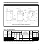
II. Specifications FIGURE 1: CGS-C BOILERS - GENERAL CONFIGURATION TABLE 1: CGS-C SPECIFICATIONS Boiler Model Approx. Shipping Weight Lbs. CGS30C 350 CGS40C 420 16 CGS50C 485 19¼ CGS60C 555 22½ CGS70C 620 25¾ CGS80C 690 29 Recommended Min. Round Chimney Size (Diameter x Height) (1) Dimensions (in inches) 'A' 'B' 'C' 12¾ 28 40-7/16 30 'D' 4 4" x 15 ft. 5 5" x 15 ft. 6 Gas Conn. (NPT) 1/2" 6" x 15 ft. 7 7" x 15 ft. 3/4" Water Volume (Gal.) Steam Boiler (2) 5.1 3.9 6.
I. Pre-Installation 1) Safe, reliable operation of this boiler depends upon installation by a professional heating contractor in strict accordance with this manual and the requirements of the authority having jurisdiction. • In the absence of an authority having jurisdiction, installation must be in accordance with this manual and the National Fuel Gas Code, ANSI Z223.1/NFPA 54.
IV. Locating the Boiler (continued) FIGURE 2: CGS-C BOILERS - CLEARANCES TO ALL TYPES OF COMBUSTIBLE CONSTRUCTION AND NONCOMBUSTIBLE CEILINGS, WALLS, AND DOORS. 4) Do not install this boiler in a location where gasoline or other flammable vapors or liquids will be stored or used. Do not install this boiler in an area where large amounts of airborne dust will be present, such as a workshop. 5) The boiler should be located as close to the chimney as possible.
V. Air for Combustion & Ventilation (continued) For Buildings of Other than Unusually Tight Construction 1) Determine whether the boiler is to be installed in a confined space - A confined space is defined by the National Fuel Gas Code as having a volume less than 50 cubic feet per 1000 BTU/hr input of all appliances installed in that space. To determine whether the boiler room is a confined space: a. Total the input of all appliances in the boiler room in thousands of BTU/hr.
V.
V.
VI. Venting Vent installation must be in accordance with local building codes, or the local authority having jurisdiction, or the National Fuel Gas Code, ANSI Z223.1/NFPA 54. A typical vent installation is illustrated by Figure 8. The components of vent installation are the vent damper (if used), vent connector and chimney.
VI. Venting (continued) 14) Install vent damper (see Figure 9) as follows: a) Open vent damper carton and remove installation instructions. Read the instructions thoroughly before proceeding. Verify that vent damper is same size as draft diverter outlet. See Figure 1. Unpack vent damper carefully. Do not force closed damper blade. Forcing vent damper closed may result in damaged gear train and void warranty.
VI.
VII. Gas Piping Gas piping to the boiler must be sized to deliver adequate gas for the boiler to fire at the nameplate input at a line pressure between the minimum and maximum values shown on the rating plate. For more information on gas line sizing, consult the utility or Chapter 2 of the National Fuel Gas Code. Figure 10 shows typical gas piping connection to the CGS-C boiler. A sediment trap must be installed upstream of all gas controls.
VIII. System Piping CAUTION • INSTALL BOILER SO THAT THE GAS IGNITION SYSTEM COMPONENTS ARE PROTECTED FROM WATER (DRIPPING, SPRAYING, RAIN, ETC.) DURING APPLIANCE OPERATION AND SERVICE (CIRCULATOR REPLACEMENT, ETC.). • OPERATION OF THIS BOILER IN A SYSTEM HAVING SIGNIFICANT AMOUNTS OF DISSOLVED OXYGEN CAN CAUSE SEVERE HEAT EXCHANGER CORROSION DAMAGE.
VIII. System Piping (continued) Piping Installation 1) Remove parts bag from boiler crate. 2) Install safety valve (spindle must be in vertical position) into tapping on boiler left side (see Figure 1) using the 3/4” NPT nipple and elbow supplied. 3) Pipe the discharge of the safety relief valve to a location where water or steam will not create a hazard or cause property damage if the valve opens. The end of the discharge pipe must terminate in an unthreaded pipe.
VIII.
IX. Indirect Water Heater Piping All CGS-C series boilers are equipped with tappings to permit the connection of a Link SL™ Indirect Water Heater, or other indirect water heater. In this type of system, hot boiler water is drawn from below the water line and passed through the heat exchanger in the indirect water heater. This section describes boiler-side piping only. Refer to Link SL™ Installation, Operating and Service Instructions for additional information.
X. Electrical WARNING All wiring and grounding must be done in accordance with the authority having jurisdiction or, in the absence of such requirements, with the National Electrical Code (ANSI/NFPA 70) 1) 120 Volt Wiring - The boiler should be provided with its own 15A branch circuit with fused disconnect. All 120 volt connections are made inside the junction box on the left side of the boiler.
X. Electrical (continued) Feeder Wiring for Boilers Equipped with McDonnell & Miller #67 Low Water Cut-offs Figures 14a and 14b show feeder wiring for McDonnell & Miller #101A, McDonnell & Miller WF2-U-24 and Hydrolevel VXT-24 feeders on boilers equipped with #67 low water cutoffs. The following points apply to all feeder wiring to #67 low water cut-offs: • Use a separate transformer to power the feeder. Do not use the transformer on the boiler.
X.
X. Electrical (continued) CGS-C Control System – Sequence of Operation (Refer to Figures 16 & 17 for ladder and connection diagrams) Sequence of Operation, Intermittent Ignition 1) When the boiler is energized, 24 volts is immediately applied to terminals “1” (blue) and “4” (yellow) on the vent damper. Assuming that there is no call for heat, and that the damper switch is in the “automatic” position, the damper will close.
X. Electrical (continued) McDonnell & Miller #67 Low Water Cut-off - Interrupts burner operation if the water in the boiler drops below a safe level. Burner operation is restored when the water level in the boiler is raised above the cut-off point. The vent damper will close when the low water cut-off interrupts burner operation. Pressure Limit Control - Interrupts burner operation when the pressure in the boiler exceeds the “Cut-in” setting plus the differential setting.
X.
FIGURE 17: LADDER DIAGRAM, McDONNELL & MILLER HYDROLEVEL CG-400A LOW WATER CUTOFF X.
X.
FIGURE 19: LADDER DIAGRAM, McDONNELL & MILLER PSE-802 LOW WATER CUTOFF X.
X.
X.
XI. System Start-up Use the following procedure for initial start-up of the boiler: 1) Make sure that the boiler is filled with water to the normal water line (28 3/4 inches above the floor or pad on which the boiler is installed) 2) Check all new gas piping for leaks and purge piping sections that are filled with air. See Part 4 of the National Fuel Gas Code for additional information on testing and purging gas lines. WARNING • NEVER USE A FLAME TO CHECK FOR GAS LEAKS.
XI. System Start-up (continued) WARNING FAILURE TO FOLLOW THE FOLLOWING PROCEDURE EXACTLY COULD RESULT IN OVERFIRING OF THE BOILER AND A CARBON MONOXIDE HAZARD. 16) Check the manifold pressure and adjust if necessary. To do this, use the following procedure: a) Connect a manometer to the inlet pressure tap on the gas valve (see Figure 25). b) Check the inlet pressure with all gas appliances on and off.
XI.
XI. System Start-up (continued) Figure 24: MAIN BURNER FLAME - 1” BURNERS 17) Test thermostat operation while the boiler is running. Turn the thermostat to the lowest setting. Both pilot burner and main burners should stop firing. Raise the thermostat back to the highest setting. The pilot burner and main burners should relight. 18) Verify low water cutoff operation while the boiler is running. Slowly open drain valve and drain boiler until the water level drops below low water cutoff line.
XI. System Start-up (continued) e) Turn off gas supply to boiler per the Operating Instructions - see Figure 23. Drain hot water from boiler through boiler drain valve to a location where hot water can be safely discharged. Refill the boiler to normal water line level. If water in the gauge glass does not look clear, repeat above boil-out procedure again until water is clears. f) Reinstall safety valve and related piping. g) Conduct pH and Alkalinity test of water in the system.
XII. Service Instructions On a continuous basis: 1) Keep the area around the boiler free and clear from combustible materials, gasoline, and other flammable vapors and liquids. 2) Keep the area around the boiler and boiler room ventilation openings clear of objects which might obstruct the flow of combustion and ventilation air.
XII. Service Instructions (continued) CAUTION LABEL ALL WIRES PRIOR TO DISCONNECTION WHEN SERVICING CONTROLS. WIRING ERRORS CAN CAUSE IMPROPER AND DANGEROUS OPERATION. VERIFY PROPER OPERATION AFTER SERVICING. 10) Inspect the vent system: • • • • Make sure that the vent system is free of obstructions. Make sure that all vent system supports are intact. Inspect joints for signs of condensate or flue gas leakage. Inspect venting components for corrosion or other deterioration.
XII. Service Instructions (continued) CAUTION If, during normal operation, it is necessary to add water to this boiler more frequently than once a month, consult a qualified service technician to check your system for leaks. A leaky system will increase the volume of make-up water supplied to the boiler which can significantly shorten the life of the boiler. Entrained in make-up water are dissolved minerals and oxygen.
XII. Service Instructions (continued) WARNING SOOT DEPOSITS IN THE FLUE PASSAGES ARE A SIGN THAT THE BOILER MAY BE OPERATING AT HIGH CARBON MONOXIDE (CO) LEVELS. AFTER CLEANING THE BOILER OF SOOT DEPOSITS, CHECK THE CO LEVEL IN THE FLUE GAS TO INSURE THAT THE BOILER IS OPERATING PROPERLY. If it is necessary to check CO, use a combustion analyzer, or other instrument which is designed to measure CO in flue gas.
XIII. Troubleshooting The following pages contain troubleshooting charts for use in diagnosing control problems. To use these charts, go to the box marked “Start” at the top of the chart on page 34 or 36 and follow the appropriate path though the chart until a box with a list of possible causes is reached. If the problem is known to be within the ignition system, go directly to the ignition system troubleshooting guide for the boiler on page 38.
XIII.
XIII.
XIII.
XIII.
XIII.
XIV. Repair Parts All CGS-C™ Series Repair Parts may be obtained through your local New Yorker Boiler Company, Inc. authorized distributor. Should you require assistance in locating a New Yorker distributor in your area, or have questions regarding the availability of New Yorker products or repair parts, please contact New Yorker’s main office: New Yorker Boiler Company, Inc. P.O. Box 10 Hatfield, PA 19440-0010 Attn: Customer Service Department www.newyorkerboiler.
XIV. Repair Parts (continued) Key No. 1 2 3 4 5 6 Description Heat Exchanger Assembly (Complete) Base Tray Base Wrapper Burner Tray Base Front Panel Assembly (includes insulation) Burner Access Panel * Not Shown 46 Part No.
XIV.
XIV. Repair Parts (continued) Key No. 7 8 9 10 11 12 Description Base End Insulation Base Rear Insulation Base Leg Assembly Screw, Self Tapping, Phillips Pan Head, 1/4 -20 x 1/2" 1/2” x 2” Sealing Strip Flame Rollout Switch Bracket Assembly Part No.
XIV.
XIV. Repair Parts (continued) Key No. Description Part No. Quantity CGS30C CGS40C CGS50C CGS60C CGS70C CGS80C 41 Main Burner with Pilot Bracket 8236098 1 1 1 1 1 1 42 Main Burner Less Pilot Bracket 43 Manifold 8236099 104810-03 104810-04 104810-05 104810-06 104810-07 104810-08 822712 822711 2 1 ----------3 --- 4 --1 ----------5 6 ----1 --------7 8 ------1 --------- 11 --------1 ------- 13 ----------1 ----- Nat. Gas Main Burner Orifice, #46 822731 --- --- --- 9 --- --- Nat.
XIV.
XIV. Repair Parts (continued) Key No. * Description Complete Jacket Set 75 Left Side Jacket Panel 76 Right Side Jacket Panel 77 Rear Jacket Panel 78 Top Jacket Panel 79 Lower Front Panel 80 Upper Front Jacket Panel 81 Diverter Panel 82 Vestibule Panel 83 84 85 86 87 * * Horizontal Jacket Clip Vertical Jacket Clip #8 X 1/2" Sheet Metal Screw Door Knob 8-32 X 1/4" H.W.H. Screw Ignition Module, UTEC 1003-664A Ignition Module Support Bracket 52 Part No.
XIV.
XIV. Repair Parts (continued) Key No. Description Part Number Quantity CGS30C CGS40C CGS50C CGS60C CGS70C CGS80C * Damper Wire Harness 105083-01 1 1 1 1 1 1 * Blocked Vent Switch Harness 104965-01 1 1 1 1 1 1 * J-Box FRS Harness 105084-01 1 1 1 1 1 1 * #67 LWCO - J-Box Harness 105987-01 1 1 1 1 1 1 * CG400 L.W.C.
XIV.
Appendix A - Tapping Locations FIGURE A1: TAPPING LOCATIONS (SEE TEXT FOR TAPPING USES) Table A1: Trim and Control Installation in Section Tappings 56 Tapping Size (NPT) A 2 Supply Supply B ½ Bush to ¼ Pressure Gauge Bush to ¼ Pressure Gauge Steam Boiler with Probe LWCO Steam Boiler with Float LWCO C ½ Gauge Glass Nipple & Union Gauge, LWCO D 2 Return Return E ¾ 3" Nipple & Street Elbow Safety Relief Valve 3" Nipple & Street Elbow Safety Relief Valve F 2 Bush to ¾ Drain Valve a
57
59