
Product Overview


16
Piping Installation
1) Remove parts bag from boiler crate.
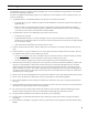
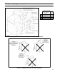
2) Install safety valve (spindle must be in vertical position) into tapping on boiler left side (see Figure 1) using the 3/4” NPT
nipple and elbow supplied.
3) Pipe the discharge of the safety relief valve to a location where water or steam will not create a hazard or cause property
damage if the valve opens. The end of the discharge pipe must terminate in an unthreaded pipe. If the safety valve
dischargeisnotpipedtoadrainitmustterminateatleast6inchesabovetheoor.Theterminationofthesafetyvalve
discharge piping must be in an area where it is not likely to become plugged by debris or subjected to freezing.
4) Install drain valve into tapping on boiler left side using the 2 x 3/4 bushing provided (see Figure 1).
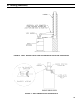
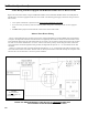
5) Connect system supply and return to boiler. See Figure 11. CGS30C through CGS60C may be piped with one or two
risers. Install 2” plug in Tapping G if optional second supply A is not used. Two supply risers are required on the
CGS70C and CGS80C.
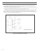
6) Piping with a Chiller - If the boiler is used in conjunction with a chiller, pipe the boiler in parallel with chiller. Use
isolation valves to prevent chilled water from entering the boiler.
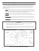
DANGER
•
PIPESAFETYVALVEDISCHARGETOASAFELOCATION.
• DONOTINSTALLAVALVEINTHESAFETYVALVEDISCHARGELINE.
• DONOTMOVESAFETYVALVEFROMFACTORYLOCATION.
• DONOTPLUGSAFETYVALVEDISCHARGE.
• DONOTINSTALLASAFETYVALVEWITHASETTINGGREATERTHAN15PSI.
VIII. System Piping (continued)