
Install Instructions

18
VII. System Start-up and Checkout
A. Main Burner Check - Check main burners to see
that they were not dislodged during shipment. Rear
of burners should be in the vertical slots in the rear of
burner tray and the front of the burners should be seated
completely on the orices.
B. Initial start -
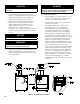
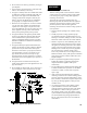
1. Fill entire heating system with water and vent
air from system. Use the following procedure on a
System equipped with zone valves. (See Figure 3).
a. Close isolation valve in boiler supply piping.
b. Isolate all circuits by closing zone valves or
balancing valves.
c. Attach a hose to hose bib located just below
isolation valve in boiler supply piping. (Note
- Terminate hose in ve gallon bucket, at a
suitable oor drain, or outdoor area).
d. Starting with one circuit, open zone valve.
e. Open hose bib.
f. Open ll valve (Make-up water line should be
located directly above isolation valve in boiler
supply piping).
g. Allow water to overow from bucket until
discharge from hose is bubble free for 30
seconds.
h. Open zone valve to the second zone to be
purged, then close the rst. Repeat this step until
all zones have been purged, but always have one
zone open. At completion, open all zone valves.
i. Close hose bib, continue lling the system
until the pressure gauge reads 12 psi. Close ll
valve. (Note - If make-up water line is equipped
with pressure reducing valve, system will
automatically ll to 12 psi. Leave globe valve
open).
j. Open isolation valve in boiler supply piping.
k. Remove hose from hose bib.
2. Turn ROOM THERMOSTAT to lowest setting.
3. Be sure that gas to pilot and main burners has been
off for at least ve minutes and vent damper has
been in the open position.
4. Turn "OFF" the electric switch serving boiler.
5. Open valve on main gas line at meter.
6. PURGE AIR FROM GAS PIPING. Adequate
ventilation must be provided and no smoking or
open ame permitted.
7. Turn "ON" electric switch serving boiler.
8. Open Manual Shut-off Valve upstream of
Combination Gas Valve.
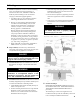
9. Loosen or remove Inlet Pressure Tap Plug in
Combination Gas Valve and when purging is
complete, tighten or replace plug. (See Figure 15).
10. Check pipe and ttings from meter to Combination
Gas Valve using soap solution or other approved
methods.
CAUTION
11. Test gas piping and connections between
Combination Gas Valve and manifold, orices, and
pilot piping for leaks after boiler is operating. Use
soap solution or other approved method.
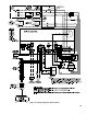
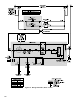
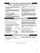
Figure 15: Top View of Honeywell Gas Valves