
Manual


12
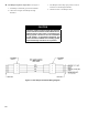
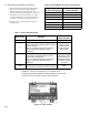
Figure 11: Vent Damper Schematic Wiring Diagram
H. Vent Damper Sequence of Operation. See Figure 11.
1. Vent Damper continuously powered at Terminal 1.
2. Call for heat energizes Vent Damper through
Terminal 5.
3. Vent Damper reaches fully open position. Power is
sent back to Limit through Terminal 2.
4. Call for heat ends. Vent Damper closes.
CAUTION
This boiler contains controls which may cause the
boiler to shut down and not restart without service.
If damage due to frozen pipes is a possibility, the
heating system should not be left unattended
in cold weather; or appropriate safeguards and
alarms should be installed on the heating system
to prevent damage if the boiler is inoperative.