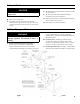
INSTALLATION, OPERATING AND SERVICE INSTRUCTIONS CG-C™ Series GAS BOILER BEFORE INSTALLATION: READ THIS MANUAL SAVE THESE INSTRUCTIONS Installing contractor and homeowner should read and be informed as to the proper installation and operation of this boiler. The manufacturer will not be responsible for improper installation or operation. This manual and all associated instruction material should be conspicuously posted near the boiler.
The following terms are used throughout this manual to bring attention to the presence of hazards of various risk levels, or to important information concerning product life. DANGER CAUTION Indicates an imminently hazardous situation which, if not avoided, will result in death, serious injury or substantial property damage. Indicates a potentially hazardous situation which, if not avoided, may result in moderate or minor injury or property damage.
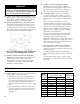
The New York City Department of Buildings has approved the CG-C Series boiler: Approval No. MEA 40-94-E. The City of New York requires a Licensed Master Plumber supervise the installation of this product. The Massachusetts Board of Plumbers and Gas Fitters has approved the CG-C Series Boiler. See the Massachusetts Board of Plumbers and Gas Fitters website, http://license.reg.state.ma.us/pubLic/pb_pre_form.asp for the latest Approval Code or ask your local Sales Representative.
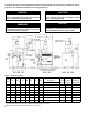
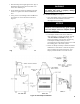
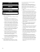
E. Provide practical service clearances. A minimum of 24" from the left side and front jacket panels is recommended for servicing but may be reduced to minimums shown in Figure 2. Subject to boiler and system piping, left side clearance may be reduced to 1" if right side clearance is increased to 9". F. Install on level floor. For basement installation provide concrete base if floor is not level or if water may be encountered on floor around boiler. G.
II. Unpack Boiler CAUTION Do not drop boiler. Do not bump boiler jacket against floor. A. Move boiler to approximate installed position. B. Remove all crate fasteners. C. Lift outside container and remove with all other inside protective spacers and bracing. Save two of the wooden slats from the container sleeve for use in Steps E and F. D. Remove all boiler hold-down fasteners. E. Tilt the boiler to one side and slide a wooden slat under the two raised feet. F.
WARNING Safety relief valve discharge piping must be piped near floor to eliminate potential of severe burns. Do not pipe in any area where freezing could occur. Do not install any shut-off valves. D. Connect system supply and return piping to boiler. E. Refer to Figure 3. Also consult I=B=R Installation and Piping Guides. Maintain minimum ½ inch clearance from hot water piping to combustible materials. Space heating and domestic water heating with the New Yorker Link SL™ indirect water heater.
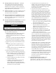
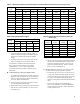
Table 3: Maximum Capacity of Schedule 40 Pipe in CFH for Natural Gas Pressures of 0.5 psig or Less 0.3 inch w.c. Pressure Drop 0.5 inch w.c.
Figure 6: Pilot and Gas Piping, Continuous Ignition (Standing Pilot) Figure 7: Pilot and Gas Piping, Intermittent Ignition (EI) V. Venting A. Install vent system in accordance with local building codes; or local authority having jurisdiction; or National Fuel Gas Code, ANSI Z223.1/NFPA 54. Install any of the following for this Classic CG-C Series Category I, draft hood equipped appliance: 1. Type B or Type L gas vent. Install in accordance with listing and manufacturer's instructions. 2.
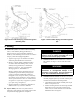
3. Slide mounting bracket tight against lower edge of Draft Hood skirt. Position #10 sheet metal screw above skirt's stiffening rib. 4. Secure bracket in position by tightening #10 sheet metal screw against outer surface of Draft Hood skirt. 5. Verify power cord, mounting bracket and Blocked Vent Switch are secure and located as shown in Figure 8. WARNING Failure to properly install and use this Blocked Vent Switch may result in property damage, personal injury or loss of life. E. Install Vent Damper.
NOTICE Provide adequate clearance for servicing. WARNING Provide 6" minimum clearance between damper and combustible construction. CAUTION Do not use one vent damper to control two heating appliances. F. Install Vent Connector from vent damper to chimney or gas vent. See Figure 10. 1. Do not connect into same leg of chimney serving an open fireplace. 2. Vent connector must not be smaller than vent damper outlet. Type B is recommended, but singlewall vent pipe may be used.
Figure 10: Typical Vent System Installation VI. Electrical A. General. Install wiring and ground boiler in accordance with requirements of authority having jurisdiction, or in absence of such requirements the National Electrical Code, ANSI/NFPA 70. B. Connect Vent Damper. See Figure 9. Install the 90° BX connector attached to the flexible conduit in the 7/8" hole on the right side of the jacket. Plug the factory wired Vent Damper Harness into polarized receptacle. C. Install thermostat.
H. Vent Damper Sequence of Operation. See Figure 11. 1. Vent Damper continuously powered at Terminal 1. 2. Call for heat energizes Vent Damper through Terminal 5. 3. Vent Damper reaches fully open position. Power is sent back to Limit through Terminal 2. 4. Call for heat ends. Vent Damper closes. CAUTION This boiler contains controls which may cause the boiler to shut down and not restart without service.
Figure 12: Wiring Diagram, Continuous Ignition (Standing Pilot) I. Sequence of Operation, Continuous Ignition (Standing Pilot). 1. Normal Operation a. Thermostat calls for heat. Vent Damper opens. b. Gas Valve energized allowing main gas flow and ignition of Main Burners. c. Call for heat ends. Gas Valve de-energized, extinguishing main flame. Vent Damper closes. 2. Safety Shutdown a. Limit: Automatically interrupts main burner operation when water temperature exceeds set point.
Figure 13: Wiring Diagram, Electronic Intermittent Ignition (EI) and skilled personnel from a qualified service J. Sequence of Operation, Electronic Intermittent agency before resetting switch. Ignition (EI). c. Flame Roll-out Switch. Automatically interrupts 1. Normal Operation boiler operation when flames or excessive heat a. Thermostat calls for heat. Vent Damper opens. are present in vestibule. Circulator continues to b. Ignition Module energized. Pilot Valve opens.
VII. System Start-up Safe lighting and other performance criteria were met with the gas manifold and control assembly provided on the boiler when the boiler underwent tests specified in American National Standard for Gas-Fired Low-Pressure Steam and Hot Water Boilers, ANSI Z21.13. A. Main Burner Check - Check main burners to see that they were not dislodged during shipment.
C. Instructions to Put the Boiler in Operation. Table 6: Ignition Module Terminal Cross-Reference 1. Electronic Ignition Modules with LED indicators. Table 6 cross-references the ignition module terminal designations to the ignition terminal numbers in the wiring ladder diagrams. The yellow LED indicates the status of the flame, see Table 7. The green LED indicates the status of the system, see Table 8.. See Figure 15 for LED locations.
Table 8: Green LED Status Codes Green LED Flash Code (X + Y)a Next System Action Recommended Service Action No “Call for Heat” N/A None Flash Fast Startup - Flame sense calibration N/A None Heartbeat Normal operation N/A None OFF 5 minute Retry DelayPilot flame not detected during trial for ignition Initiate new trial for ignition after retry delay completed.
Figure 16: Operating Instructions 18
Figure 17: Lighting Instructions 19
D. Check Gas Input to Boiler NOTICE CG-C boilers built for installation at altitudes greater than 2,000 feet above sea level have been specially orificed to reduce gas input rate 4 percent per 1,000 feet above sea level per the National Fuel Gas Code, NFPA 54/ANSI Z223.1. High altitude boiler models are identifiable by the third digit in the model number suffix on the rating label: CG_OC- _ _ 2: less than 2000 ft. elevation CG_OC- _ _ 5: 2000 to 5000 ft. elevation 1.
F. Check Pilot Burner Flame. 1. Continuous Ignition (Standing Pilot, Natural Gas), Models 20 through 70 and Model 20 (Standing Pilot, LP). See Figure 19. Pilot burner produces a single flame. The flame should be steady, medium hard blue enveloping 3/8 to 1/2 inch of thermocouple. 2. Continuous Ignition (Standing Pilot, Natural and LP Gas), Models 80 through 100 and Continuous Ignition (Standing Pilot, LP gas), Models 30 through 70. See Figure 20. Pilot burner produces three (3) flames.
Honeywell Electronic Ignition Trouble Shooting Guide 22
VIII. Service WARNING Service on this boiler should be undertaken only by trained and skilled personnel from a qualified service agency. Inspections should be performed at intervals specified in this manual. Maintain manual in a legible condition. Keep boiler area clear and free of combustible materials, gasoline and other flammable vapors and liquids. Do not place any obstructions in boiler room that will hinder flow of combustion and ventilation air. A. General.
flame roll-out switch wires, pilot gas supply, thermocouple lead or pilot lead. 7. For Continuous Ignition (Standing Pilot) connect thermocouple at gas valve. For Intermittent Ignition (EI) connect pilot gas supply, igniter/sensor wire, and ground wire at Ignition Module. 8. Install Burner Access Panel. Connect Flame Rollout Switch wires. F. Check Operation. Follow steps C through J from Section VII: System Start-up. G. Removal or replacement of pilot assembly or pilot assembly parts.
IX. Repair Parts All Classic CG-C™ Series repair parts may be ordered through New Yorker Boiler Co., Inc. or its authorized distributors. Should you require assistance in locating a New Yorker Distributor in your area, or have questions regarding the availability of New Yorker products or repair parts, please contact: New Yorker Boiler Co., Inc. P.O.
Key No.
Section Assembly and Canopy Group 27
Key No.
Key No.
Key No.
Manifold and Main Burners (1 Inch Main Burners) 31
Key No.
Manifold and Main Burners (40mm Main Burners) 33
Key No. Description Part Number CG-C MODEL 20 30 40 50 60 70 80 90 100 Continuous Ignition (24V Standing Pilot) - 1 Inch and 40mm Main Burners Pilot Burner and Gas Valve, Natural & LP Gas 33 Pilot Burner, Honeywell Q350A1321 (Nat. Gas) 8236065 1 1 1 1 1 *1 --- --- --- Pilot Burner, Honeywell Q327A1006 (Nat.
Key No.
Key No.
SERVICE RECORD DATE 40 SERVICE PERFORMED
SERVICE RECORD DATE SERVICE PERFORMED 41
SERVICE RECORD DATE 42 SERVICE PERFORMED
X. Low Water Cut Off (LWCO) on Hot Water Boilers WARNING DO NOT ATTEMPT to cut factory wires to install an aftermarket Low Water Cut Off (LWCO). Only use connections specifically identified for Low Water Cut Off. In all cases, follow the Low Water Cut Off (LWCO) manufacturer's instructions. When A low water cutoff is required to protect a hot water boiler when any connected heat distributor (radiation) is installed below the top of the hot water boiler (i.e.
NEW YORKER BOILER CO., INC. Limited Warranties For Residential Cast Iron and Steel Water Boilers By this Warranty Statement New Yorker Boiler Co., Inc. ("New Yorker"), issues limited warranties subject to the terms and conditions stated below. These limited warranties apply to residential cast iron and steel water boilers labeled with the New Yorker® brand which are sold on or after March 1, 2004.