
User Guide


20
VIII. Operation
A. BOILER SEQUENCE OF OPERATION
NORMAL OPERATION
1. The CG-E Series Boilers are equipped with an
Integrated Boiler Control (IBC). This IBC replaces
the traditional separate ignition control, high limit
switch and circulator relay and adds energy saving
thermal purge features. Energy is saved by starting
the circulator and delaying the burner start when
there is residual heat available in the boiler.
2. The boiler’s sequence of operation is shown in
Table 2.
3. When the thermostat calls for central heat (CH) the
IBC starts the system circulator and the thermal
purge begins. If the boiler temperature is less than
140°F, the start sequence continues by energizing
the vent damper. Once the vent damper is fully
open the ignition sequence is started allowing gas
in open position when appliance main burners are
operating.
setpoint is reached the system circulator will
continue to operate and the burners will stop.
When the boiler water temperature drops below the
setpoint less the differential setting the burners will
restart.
circulator are stopped and vent damper is closed.
6. When an indirect water heater aquastat call for
the circulator and, if the boiler temperature is less
than the operating setpoint less differential, the vent
damper is energized without delay. Once the vent
damper is fully open, the ignition sequence is started
high limit will match CH set point if CH set point is
below 200°F.
NOTICE
DHW Thermostat should only be used for systems
with zone valves, see Figure 5.
B. BOILER FAULT
In the event the boiler fails to start, the control provides
status information to help determine the cause of the
problem. Table 3 from Section X: Troubleshooting
the source of the lockout. Refer to the Troubleshooting
Section for more information.
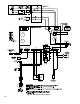
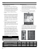
C.
The control is located inside the boiler. (Figure 17).
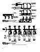
Status POWER TSTAT/CIRC LIMIT DAMPER FLAME
1 Standby
2 Call for heat - Circulator on
3 Limit circuit closed
4 Vent Damper - Proven open
5 Pilot ame proven
Figure 17: Integrated Boiler Control
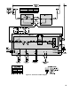
Figure 18: Boiler Display
The IBC display, along with two adjustment knobs may
located to the right of the display. When powered the
light up red depending on the state of the control (see
Figure 18).
- LED illuminated
- LED off
Table 2: Sequence of Operation Using the Controls LEDs