
User Guide


10
IV. Venting
A. Install Vent Damper
OPEN THE VENT DAMPER CARTON and remove the
Installation Instructions. READ THE INSTALLATION
INSTRUCTIONS THOROUGHLY before proceeding.
The automatic gas control valve supplied on each
CG-E Series boiler provides the redundancy referenced
in the vent damper Installation Instructions.
CAUTION
Do not use one vent damper to control two heating
appliances.
1. The vent damper must be the same size as the outlet
of the Draft Hood supplied with the boiler (see
Table 1A). Unpack the damper carefully - DO NOT
FORCE IT CLOSED! Forcing the damper may
damage the gear train and void the warranty.
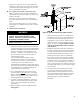
2. Mount the vent damper assembly onto the canopy/
diverter. (Refer to Figure 7 and to instructions
packed with the vent damper for specic
instructions). Do not modify either the draft hood or
vent damper.
NOTICE
Provide adequate clearance for servicing.
3. Locate vent damper position indicating means to be
visible following installation.
WARNING
Provide 6" minimum clearance between damper
and combustible construction.
4. Plug the factory harness vent damper connector into
damper motor polarized receptacle.
DANGER
Inspect existing chimney before installing boiler.
Failure to clean or replace perforated pipe or tile
lining will cause severe injury or death.
B. Inspect chimney and remove any obstructions or
restric tions. Clean chimney if previously used for solid
or liquid fuel-burning appliances or replaces.
C. Install vent system in accordance with "Venting of
Equipment" of the National Fuel Gas Code, ANSI
Z223.1/NFPA 54, or applicable provisions of local
building codes. The CG-E Series boiler is a Category I,
draft hood equipped appliance.
WARNING
D. If an Existing Boiler is Removed:
When an existing boiler is removed from a common
venting system, the common venting system is likely
to be too large for proper venting of the appliances
remaining connected to it.
At the time of removal of an existing boiler, the
following steps shall be followed with each appliance
remaining connected to the common venting system
placed in operation, while the other appliances
remaining connected to the common venting system are
not in operation:
a. Seal any unused openings in the common venting
system.
b. Visually inspect the venting system for proper
size and horizontal pitch and determine there is no
blockage or restriction, leakage, corrosion, and other
deciencies which could cause an unsafe condition.
c. Insofar as is practical, close all building doors and
windows and all doors between the space in which
the appliances remaining connected to the common
venting system are located and other spaces of the
Figure 7: Vent Damper Installation