INSTALLATION, OPERATING AND SERVICE INSTRUCTIONS CG-E™ Series GAS BOILER 9700609 BEFORE INSTALLATION: READ THIS MANUAL SAVE THESE INSTRUCTIONS Installing contractor and homeowner should read and be informed as to the proper installation and operation of this boiler. The manufacturer will not be responsible for improper installation or operation. This manual and all associated instruction material should be conspicuously posted near the boiler.
The City of New York requires a Licensed Master Plumber supervise the installation of this product. The Massachusetts Board of Plumbers and Gas Fitters has approved the CG-E™ Series Boiler. See the Massachusetts Board of Plumbers and Gas Fitters website, http://license.reg.state.ma.us/pubLic/pl_products/pb_pre_form.asp for the latest Approval Code or ask your local Sales Representative. The Commonwealth of Massachusetts requires this product to be installed by a licensed Plumber or Gas fitter.
Table 1A: Dimensions and Connections Boiler Model Depth CG30E 32 Width Height 14 40 Supply NPT Return NPT Vent Gas NPT Relief Valve Drain (inch) (inch) (inch) (inch) NPT (inch) NPT (inch) 1¼ 1¼ 4 ½ ¾ ¾ CG40E 32 16 40 1¼ 1¼ 5 ½ ¾ ¾ CG50E 32 19 40 1¼ 1¼ 6 ½ ¾ ¾ CG60E 32 22 40 1¼ 1¼ 6 ½ ¾ ¾ CG70E 32 25 40 1¼ 1¼ 7 ¾ ¾ ¾ CG80E 32 28 40 1¼ 1¼ 7 ¾ ¾ ¾ CG90E 32 31 40 1¼ 1¼ 8 ¾ ¾ ¾ Table 1B: Inputs, Weights and Volumes Boiler Model (1) Input (
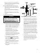
Figure 1: Minimum Clearance to Combustible Materials and Alcove Dimensions 4
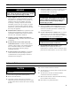
I. Pre-Installation WARNING Carefully read all instructions before installing boiler. Failure to follow all instructions in proper order can cause personal injury or death. A. Inspect shipment carefully for any signs of damage. All equipment is carefully manufactured, inspected and packed. Our responsibility ceases upon delivery of boiler to carrier in good condition. Any claim for damage or shortage in shipment must be filed immediately against carrier by consignee.
III. Water Piping and Trim WARNING Failure to properly pipe boiler may result in improper operation and damage to boiler or building. A. Design and install boiler and system piping to prevent oxygen contamination of boiler water. Oxygen contamination sources are system leaks requiring addition of makeup water, fittings, and oxygen permeable materials in distribution system.
Adjust valves to provide 180° to 200°F supply water temperature. Opening the boiler supply valve will raise system temperature, while opening by-pass valve will lower system supply temperature. H. If it is required to perform a long term pressure test of the hydronic system, the boiler should first be isolated to avoid a pressure loss due to the escape of air trapped in the boiler. To perform a long term pressure test including the boiler, ALL trapped air must first be removed from the boiler.
Figure 5: Recommended Water Piping for Zone Valve Zoned Heating Systems
Figure 6: Recommended Water Piping for Circulator Zoned Heating Systems
IV. Venting A. Install Vent Damper OPEN the VENT DAMPER CARTON and remove the Installation Instructions. READ THE INSTALLATION INSTRUCTIONS THOROUGHLY before proceeding. The automatic gas control valve supplied on each CG-E Series boiler provides the redundancy referenced in the vent damper Installation Instructions. CAUTION Do not use one vent damper to control two heating appliances. 1. The vent damper must be the same size as the outlet of the Draft Hood supplied with the boiler (see Table 1A).
building. Turn on clothes dryers and any appliance not connected to the common venting system. Turn on any exhaust fans, such as range hoods and bathroom exhausts, so they will operate at maximum speed. Do not operate a summer exhaust fan. Close fireplace dampers. d. Place in operation the appliance being inspected. Follow the Lighting (or Operating) Instructions. Adjust thermostat so appliance will operate continuously. e.
V. Gas Piping A. Size gas piping. Design system to provide adequate gas supply to boiler. Consider these factors: 1. Allowable pressure drop from point of delivery to boiler. Maximum allowable system pressure is ½ psig. Actual point of delivery pressure may be less; contact gas supplier for additional information. Minimum gas valve inlet pressure is listed on rating label. 2. Maximum gas demand. Consider existing and expected future gas utilization equipment (i.e. water heater, cooking equipment). 3.
VI. Electrical A. General. Install wiring and electrically bond boiler to ground in accordance with requirements of authority having jurisdiction, or in absence of such requirements, with the National Electrical Code, ANSI/NFPA 70. B. Install thermostat. Locate on inside wall approximately 4 feet above floor. Do not install on outside wall, near fireplace, or where influenced by drafts or restricted air flow, hot or cold water pipes, lighting fixtures, television, or sunlight.
Figure 9: Wiring Connection Diagram 14
Figure 10: Schematic Ladder Diagram 15
Figure 11: Wiring Schematic, Zone Valves Figure 12: Wiring Schematic, Zone Circulators 16
VII. System Start-up and Checkout A. Main Burner Check - Check main burners to see that they were not dislodged during shipment. Rear of burners should be in the vertical slots in the rear of burner tray and the front of the burners should be seated completely on the orifices. B. Initial start 1. Fill entire heating system with water and vent air from system. Use the following procedure on a System equipped with zone valves. a. Close isolation valve in boiler supply piping. b.
Figure 14: Operating Instructions 18
4. With boiler off, water Manometer or water column gauge should be connected to a shut-off valve installed in the 1/8" outlet pressure tap in the gas valve (see Figure 13). By installing gas valve upstream of manometer, gas pressure can be introduced gradually - without shut-off valve; surge of pressure when boiler is turned on, could blow liquid out of manometer. Replace plug in gas valve when rate check is finished. 5.
VIII. Operation B. BOILER FAULT A. BOILER SEQUENCE OF OPERATION In the event the boiler fails to start, the control provides status information to help determine the cause of the problem. Table 3 from Section X: Troubleshooting (page 24) provides a list of boiler flash codes indicating the source of the lockout. Refer to the Troubleshooting Section for more information. NORMAL OPERATION 1. The CG-E Series Boilers are equipped with an Integrated Boiler Control (IBC).
1. High limit setpoint The High Limit Setpoint is user adjustable by turning the top knob labeled “BOILER TEMP”. Adjustment range is 140°F to 220°F. During normal operation the LED display will show boiler temperature. When a change is made to the setpoint knob the display will brighten and show the setpoint. Factory programmed with High Limit Setpoint of 140°F. 2.
IX. Service and Maintenance Important Product Safety Information Refractory Ceramic Fiber Product Warning: The Repair Parts list designates parts that contain refractory ceramic fibers (RCF). RCF has been classified as a possible human carcinogen. When exposed to temperatures above 1805°F, such as during direct flame contact, RCF changes into crystalline silica, a known carcinogen.
WARNING Service on this boiler should be undertaken only by trained and skilled personnel from a qualified service agency. Inspections should be performed at intervals specified in this manual. Maintain manual in a legible condition. Keep boiler area clear and free of combustible materials, gasoline and other flammable vapors and liquids. Do not place any obstructions in boiler room that will hinder flow of combustion and ventilation air. A. General. Inspection and service should be conducted annually.
X. Troubleshooting A. Before troubleshooting The following pages contain troubleshooting tables for use in diagnosing control problems. When using these tables the following should be kept in mind: 1. This information is only meant to be used by a professional heating technician as an aid in diagnosing boiler problems. 2. In general, these tables assume that there are no loose or miswired electrical connections.
B. Use Control LEDS To Direct TroubleShooting Efforts If the control detects an error, the LEDs will flash. Use the LEDs to identify the boiler problem and corrective action in the table below. If LEDs are not flashing, proceed to Paragraph C: Flashing LEDs Status Recommended Corrective Action Boiler or Control is not powered No 120 Vac Power at boiler, check breaker and wiring between breaker panel and boiler POWER Steady 1 Hz flash Line Voltage Reversed Reverse polarity of 115 VAC supply voltage.
C. Use status LEDS To guide TroubleShooting The control LEDs will light to indicate status. Use these LEDs to identify the boiler problem in the table below: 1. Boiler and Circulator Off LED / Status Recommended Corrective Action The boiler has not detected a call for heat - POWER Standby Burner off Circulator off Check that the thermostat: - When a thermostat call for heat is detected control TSTAT/CIRC LED will be lit.
4. Circulator is On But Damper is Not Open LED / Status Recommended Corrective Action The control is waiting for the damper to open. Damper end switch has failed to close (end switch contact is stuck open). Combustion can never take place unless the damper blade is in the fully open position. Check the following: - POWER - TSTAT/CIRC - LIMIT Damper Failed to Open - Confirm if control terminal “P6 - 5” (yellow wire) is energized.
5. Circulator is On, Damper is Open But Boiler Fails to Start (continued) LED / Status Recommended Corrective Action 1. No Spark a. Can you hear sparking? - If there is no spark noise replace the control. b.
XI. Repair Parts All CG-E™ Series repair parts may be ordered through New Yorker Boiler Company, Inc. or its authorized distributors. Should you require assistance in locating a New Yorker Distributor in your area, or have questions regarding the availability of New Yorker products or repair parts, please contact: New Yorker Boiler Company, Inc. P.O. Box 10 Hatfield, Pennsylvania 19440-0010 Attn: Customer Service Department www.newyorkerboiler.
Key No.
Section Assembly and Canopy Group 31
Key No.
Key No.
Key No. Description Part Number CG-E MODEL 30 40 50 60 70 80 90 Burners, Manifold and Gas Valve (Natural & LP Gas) 3A Gas Valve, Honeywell VR8204P1171 (Nat. Gas) 81660282 1 1 1 1 --- --- --- Gas Valve, Honeywell VR8304P4496 (Nat.
Key No. Description Part Number CG-E MODEL 30 40 50 60 70 80 90 Controls 4A Boiler Control, Atmospheric Draft, UTEC 1135-630 106541-01 1 1 1 1 1 1 1 4B Transformer, 40 VA, modified Honeywell AT140B1297 106529-01 1 1 1 1 1 1 1 4C Limit Rated Temperature Sensor, 12" Lg.
Key No.
Key No. Description Part Number CG-E MODEL 30 40 50 60 70 80 90 8060700 1 1 1 1 1 1 1 Trim and Vent Damper 6A Supply Water Manifold 6B Temperature / Pressure Gauge 100282-01 1 1 1 1 1 1 1 6C Safety Relief Valve, 30 psi 81660363 1 1 1 1 1 1 1 6D Drain Valve 102802-01 1 1 1 1 1 1 1 Vent Damper - 4" Dia. 102284-01 1 --- --- --- --- --- --- Vent Damper - 5" Dia. 102284-02 --- 1 --- --- --- --- --- Vent Damper - 6" Dia.