
User Guide

11
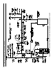
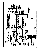
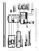
line as illustrated in Figures 6A and 6B in order
to regulate water ow for maintenance of higher
boiler water temperature. Set the bypass and
return valves to a half throttle position to start.
Operate boiler until the system water temperature
reaches its normal operating range. Adjust the
valves to maintain 180°F to 200°F boiler water
temperature and greater the 120°F return
temperature. Adjust both valves simultaneously.
Closing the boiler return valve while opening the
bypass valve will raise the boiler return
temperature. Opening the boiler return valve
while closing the by-pass valve will lower the
boiler return temperature.
e. A water boiler installed above radiation level
must be provided with a low water cutoff device
as part of the installation.
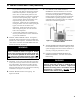
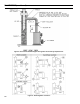
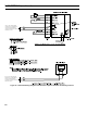
B. INSTALL SAFETY RELIEF VALVE. See Figures 5,
6A and 6B. Safety Relief Valve must be installed with
spindle in the vertical position. Installation of the relief
valve must be consistent with ANSI/ASME Boiler and
Pressure Vessel Code, Section IV.
WARNING
Installation is NOT complete unless a safety relief
valve is installed as shown in Figure 5. Safety
(relief) valve discharge piping must be piped near
oor to eliminate potential of severe burns. DO
NOT pipe in any area where freezing could occur.
DO NOT install any shut-off valves, plugs or caps.
C. AIR VENT. An air vent or purge must be incorporated
in the system to easily remove air from the boiler when
the system is lled. The boiler has a built in dip tube
which works with the air vent to clear the boiler of air.
Improper application of the air vent will cause steaming
in the boiler. See Figures 5, 6A and 6B.
D. INSTALL DRAIN VALVE in return piping. See
Figures 6A and 6B.
E. OIL, GREASE, AND OTHER FOREIGN
MATERIALS which accumulate in new hot water
and a new or reworked system should be boiled
out, and then thoroughly ushed. A qualied water
treatment chemical specialist should be consulted for
recommendations regarding appropriate chemical
compounds and concentrations which are compatible
with local environmental regulations.
Figure 5: Air Vent and Safety Relief Valve
Installation Detail
F. AFTER THE BOILER AND SYSTEM HAVE BEEN
CLEANED and ushed, and before relling the entire
system add appropriate water treatment chemicals, if
necessary, to bring the pH between 7 and 11.
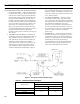
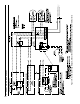
G. CONNECT TANKLESS HEATER PIPING AS
SHOWN IN FIGURE 7. See Table 3 for Tankless
Heater Rating.
WARNING
Install automatic mixing valve at tankless heater
outlet to avoid risk of burns or scalding due to
excessively hot water at xtures. Adjust and
maintain the mixing valve in accordance with the
manufacturer's instructions. DO NOT operate
tankless heater without mixing valve.
III: WATER PIPING AND TRIM (continued)