Omnia ONE Multicast ® Audio Processor with Installation and Operation Manual Version 0.9i / March 2007 Applicable to v1.0 Release Software A Telos Company Omnia ● 2101 Superior Avenue Cleveland, Ohio 44114 USA TEL: +1 216.241.7225 ● FAX: +1 216.241.4103 ● Email info@omniaaudio.com www.omniaaudio.com Omnia Europe ● Johannistrabe 6 D-85354 Freising Germany TEL: +49 8161 42467 ● FAX +49 8161 42402 ● Email: europe@omniaaudio.com www.omniaaudio.
OmniaONE Multicast - Use and Operation Manual – Version 0.
January, 2007 Welcome to Omnia.ONE! I wish to offer my sincere gratitude on behalf of our company and welcome you to Omnia.ONE! This manual was assembled by a dedicated team of specialists who were instrumental in the development of our newest product, Omnia.ONE. This is our next step in the never-ending quest to build the best signal processor in the world. Considerably more powerful than what its small package implies, Omnia.
OmniaONE Multicast - Use and Operation Manual – Version 0.
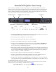
OmniaONE Quick-Start Setup We know that you’re probably in a hurry to begin using your new OmniaONE Multicast. If you have technical expertise and previous knowledge of audio processor fundamentals, using our Nine-Point QuickStart will get you up and running as quickly as possible. Please refer to the remainder of the Operating Guide for additional installation and setup information.
Table Of Contents Welcome to Omnia.ONE! .............................................................................................. 3 OmniaONE Quick-Start Setup........................................................................................ 5 Sensus® Technology: Audio Processingx3 ...................................................................... 9 Overview ....................................................................................................................
Chapter-4: Main Menu Selections................................................................................. 31 Preset........................................................................................................................ 31 Processing ................................................................................................................ 31 Save Preset ............................................................................................................ 32 Delete Preset .
Appendix A: Performance Specifications..................................................................... 49 Appendix B: Troubleshooting/Service/Warranty........................................................ 53 Diagnostic and Error Messages ............................................................................. 53 Electrical and mechanical safety note!.................................................................. 54 Narrowing down problems.......................................................
.Multicast Sensus® Technology: Audio Processingx3 Overview Until now, digital signal processing has been a more precise numeric implementation of well-known analog methods.
and bandwidth limiting methods that were required for analog broadcasting, as well as for the signal normalization techniques used in recording and mastering. Audio codecs on the other hand are moving targets - each codec algorithm has its own set of artifacts. So not only does the sonic quality vary depending on the algorithm and bitrate used, but more importantly they vary in their ability to mask their own coding action.
So… what’s so smart about Sensus®? The fact is, Sensus® is smart. In real time it predicts program content that will be troublesome for the codec, and by modifying it’s own algorithms can make appropriate changes to the program material before it ever reaches the codec!1 The result is consistently high audio quality through a codec-based system, even at very low (18kbps – 21kbps) bitrates. The human voice is very difficult to code at low bitrates without quality and intelligibility suffering.
SAFETY INSTRUCTIONS 1. Read All Instructions. All safety and operating instructions must be read before operating the product. 2. Retain All Instructions. All safety and operating instructions must be retained for future reference. 3. Heed All Warnings. All warnings on the product and those listed in the operating instructions must be adhered to. 4. Follow All Instructions. All operating and product usage instructions must be followed. 5. Heat.
HAZARD / WARNING LABELS The Exclamation Point symbol, within an equilateral triangle, alerts the user to the presence of important operating and maintenance (servicing) instructions in product literature and instruction manuals. The Lightning Flash With Arrowhead symbol, within an equilateral triangle, alerts the user to the presence of noninsulated dangerous voltages within the product's enclosure that may be of sufficient magnitude to constitute a risk of electric shock.
CE CONFORMANCE – This device complies with the requirements of the EEC Council Directives: 93/68/EEC (CE Marking); 73/23/EEC (Safety – low voltage directive); 89/336/EEC (electromagnetic compatibility). Conformity is declared to those standards: EN50081-1, EN50082-1. LITHIUM BATTERY CAUTION – There is a danger of explosion if the internal battery is replaced incorrectly or shorted. Replace the battery only with same or equivalent type recommended by the manufacturer.
Manual Update Notification Audio Processing – a unique art form that we take very seriously! As part of our dedication to the science of audio processing we will continue to improve and update the Omnia product and its documentation based on our ongoing research, real-world field experience, and the valued input from our many thousands of loyal customers.
Chapter-1: Installation Pre-Installation Tasks Please take a few minutes to read through this chapter before proceeding with the installation. This section offers common procedures for installing your new OmniaONE processor. About This Manual This manual is written to cover the OmniaONE Multicast. If you are setting up a different version of the OmniaONE, please refer to the instruction manual for that product. OmniaONE Components By now, you’ve unpacked the shipping carton to gain access to this manual.
Installation & Connections Throughout this section reference is made to “software parameters.” These are part of the User Interface, which is covered in detail in Chapter 2. Rack Mounting The OmniaONE requires one RU (1.75" [44.45 mm]) of rack space. Rack mount the unit using four rack screws. If only two screws are going to be used, they should be in the bottom holes in the Omnia front panel.
Rear Panel Connections Analog Audio Inputs and Outputs Balanced XLR-type connectors are used as input connectors for the analog audio. Both analog and digital input sources may be connected simultaneously, however, only the input source that has been selected is active. Analog/Digital/Livewire Input source selection is done through the “Source” software parameter setting in the Input/Output / Input Menu. The stereo analog inputs are designed for standard +4dBu balanced signals. Pin 2 is Hot.
AES/EBU Digital Input, AES/EBU External Sync Input, and AES/EBU Output The digital AES/EBU (AES-3) inputs (IN and EXT. SYNC) use industry-familiar RJ-45 connectors and utilize the StudioHUB+ wiring standard1. They accept any sampling rate between 32kHz and 96kHz. No user adjustment of the sample rate is necessary on the AES-3 input as a high-quality digital sample rate converter is built in.
RS-232 Modem Connection (DB-9F) This DB9-female connector can be used to connect an external dialup modem for a bi-directional computer remote control connection.1 NOTE: This connector is for a remote control external modem connection only. Please see Appendix B for information on how to use a terminal program along with an internal RS-232 connector for troubleshooting purposes.
General Purpose Interface (GPI) (DB-9M) This DB9-male connector serves as a four-input, optoisolated interface to the Omnia's internal trigger script functions. Four of the pins are “trigger” inputs, four are “ground” and the remaining pin is +5V power. The trigger inputs can be used to dynamically alter the OmniaONE’s operation in response to logic transitions on the interface connection. Virtually any parameter of the Omnia can be controlled using the Trigger Scripts.
Chapter-2: Getting To Know Your OmniaONE The OmniaONE User Interface Now that your OmniaONE is rack-mounted, connected to a program audio source, and turned on, you’re ready to learn how to operate it! This chapter covers the Front Panel User Interface, your window into the OmniaONE processor.
Audio I/O Level Display Either input or output levels can be displayed. The highest LED illuminated indicates digital sample-accurate peak signal levels. The meters are calibrated in decibels below full scale digital (0 dBFS), which is the absolute maximum level in the digital domain. Audio I/O Level Display Processing Meter Display In “Meter Display” Mode the vertical bargraphs show all of the processing activity of the AGC and Limiter sections within the OmniaONE.
Using the Jog Wheel The main user control for the OmniaONE is the easy to use jog wheel with its integral push-switch. Using the control is both intuitive and efficient, making it easy to navigate the menu structure of the OmniaONE. Processing changes and system adjustments can be quickly made with ease without having to remember multiple controls, their positions, and what they do in each menu. The behavior of the OmniaONE's menu system is consistent across pages and is easy to learn.
Main Menu The OmniaONE menu system has been designed to be intuitive and simple to use. Most operating parameters are found under one of the menu headings and sub-headings, allowing adjustments to be made quickly and with ease. Rotating the jog-wheel sequentially highlights each menu item in turn. When the jog wheel is pressed inward (clicked) while a menu item is highlighted it will open that item’s submenu. Similar behavior occurs when selections are made within the various submenus.
¾ The factory default selection for Input Source is Analog. To change the input selection to AES/EBU digital, rotate the jog-wheel until [AES/EBU] is displayed and click. If you are using the analog inputs, rotate the jog wheel to display [Analog] and click to reselect the analog inputs. ¾ To return to the top level of the Main Menu, rotate the jog-wheel to highlight <-EXIT and click. Repeat until the top level (Main Menu) is reached.
Chapter-3: Getting The Sound You Want In general, applications requiring audio processing prior to a codec don’t rely heavily on absolute loudness for their overall success. Loudness is still important of course – you do want to be heard – but it is not the most important thing.
The following sections are provided to assist you in designing the personality of your sound. As we said earlier, there is no precise recipe for setting up audio processing because each application is different. However there are a few basics that we can share with you that can help get you to where you want to go.
Some users prefer their processing to be perceptibly loud but very dynamic. While this may not result in the loudest sound, it gives the illusion of competitive loudness while still retaining a lot of detail and clarity. To achieve this sound you should target most adjustments to the Limiter sections, and avoid heavy use of the Final Limiter and fast settings in the AGC sections.
The last option, adjusting the Mixer, is designed to provide a final minor trim to the audio spectrum. Since this stage is after all of the dynamic multi-band AGC and Peak Limiting, a radical change in level in the Mixer could result in excessive look-ahead final limiting in that band’s frequency range. We suggest that any changes implemented here be limited to about 0.5 dB to 0.7 dB of boost maximum.
Chapter-4: Main Menu Selections This section presents an overview of the five Main Menu items, (Preset:, Processing, Input/Output, Administrative and Lock Front Panel) their submenus (if any), and details about each of the adjustable controls within. Preset OmniaONE is equipped with a selection of factory presets that can be used to instantly configure the processing for common applications. The currently loaded preset is displayed to the right of Preset: on the top line of the Main Menu.
Save Preset This option saves any changes you have made to the currently running preset into the OmniaONE’s non-volatile memory. Changes can be saved over an existing user preset (without renaming it) or as a new user preset with a new name. You may not save a factory preset over itself with the same name and attempting this will generate the error message: “Cannot overwrite factory preset. Save preset with new name.” Presets can contain up to 10 characters.
Rename Preset A preset in the list of stored user presets can be renamed at any time. Factory presets cannot be renamed. To rename a user preset highlight Rename Preset and click. Rotate the jog wheel to display the preset to be renamed and click. Edit the preset name as described above in the Save Preset section. To exit without renaming the preset, rotate the jog wheel until *cancel* is displayed and click. <-Exit Click on this option to return to the Main Menu.
WB AGC (Bypass, Engage) The wideband Automatic Gain Control (AGC) stage can be bypassed if desired, although more consistency is achieved when this stage is used. AGC Drv (AGC Drive) This control adjusts the amount of drive to the wideband AGC stage. Increasing the drive causes deeper compression to be achieved, and deeper compression allows quieter passages in the input audio to be raised further than if lesser drive (and less compression) was used.
not actually capable of producing because the human brain equates the presence of low frequency harmonics to the missing fundamentals that the small speaker is unable to reproduce. On systems with larger speakers, the effect of Phat Bass becomes subtler because the extended frequency response of those systems allows the fundamentals of the low notes to be heard, masking the added harmonics contributed by Phat Bass.
The release control adjusts how fast the AGC recovers from periods of more gain reduction when the input audio levels fall. Faster release times (higher numbers) result in a more dense sound. Even though the Omnia uses program controlled release algorithms, setting the control for extremely fast release times can result in ‘pumping’. Gt Thresh (Gate Threshold) When the input audio falls below a certain level, the gain control action of the AGC stage is “frozen” by the gate.
The attack control adjusts how fast the limiter responds to sudden increases in audio level, and higher numbers equate to faster response times. Faster attack times reduce the transient nature of the input audio, while slower attack times improve it. Extremely slow attack times must be used with caution because allowances must be made in the following final limiter stage so as not to overload it during the time when the limiter is adjusting the level downwards.
Adjusts the output level of the presence band limiter into the overall mix. Higher numbers result in more presence frequencies and too much mix level can make the following final limiter work unnecessarily hard. Hi Band Adjusts the output level of the high band limiter into the overall mix. Higher numbers result in more high frequencies and too much mix level can make the following final limiter work unnecessarily hard. <-Exit Click on this option to return to the Adjust Processing submenu.
Final Limit Drive The Drive control controls the depth of final limiting. The amount of gain-reduction occurring in the final limiter can be monitored on the Process metering bargraph screen. Note, however, that this meter cannot show extremely fast action in the limiter, so your ear must be the final judge. LPF Freq (Low Pass Filter Frequency) This is a key control and is used for matching the audio bandwidth of the processed audio to the bitrate of a following codec.
1 The Nyquist Theorem states that the maximum frequency that may be applied to a sampled data system is one half the sampling frequency.
Mtr Select (Meter Select) Selects whether the Input levels or Output levels are displayed on the front panel L & R LED bargraph meters. Please note that in the initial release software the meters when set to monitor Output levels will only monitor the analog outputs. Input There are nine controls under the heading “Input” and each will be explained in the order in which they appear in the menu: <-Exit Click on this option to return to the Input/Output submenu.
Allows a +/-3dB adjustment of the right digital audio channel gain to correct minor left/right balance problems in the input audio. The left channel digital input gain is not affected by this control and is set using the master AES Level control previously described. Invert Permits audio phase inversion to be performed in the following combinations: [None] – [Both] – No Channel inversion is performed (factory default) Both left and right channel phase is inverted.
Configures the DSP processing chain to swap the Left and Right internal channels, that is, the DSP Left Channel is fed from Right Channel input and the DSP Right Channel is fed from the Left Channel input. Note that this selection is active in all sources selected as Primary and Secondary (Failover) audio sources. <-Exit Click on this option to return to the Input/Output submenu.
Slaves the output sample rate to the sample rate present on the Omnia’s AES SYNC input. Synchronization is possible over a range of sample rates from 32kHz to 96kHz. <-Exit Click on this option to return to the Input/Output submenu. Bypass [Process] This is the normal default setting where all processing will be active. [Bypass] This setting will bypass all processing for test purposes.
appears. Now rotate the knob to select the desired character for it and click to accept. (Note that this inserts a new character before the one selected, and keeps the originally selected character intact as what it was before choosing "^") When you are finished, simply rotate the knob clockwise with the cursor in “select” mode until the Save button is highlighted and click to save the configuration preset.
Several maintenance and utility functions are found in this submenu including various Security options to prevent tampering by unauthorized personnel, TCP/IP networking parameters and other system-wide parameters. About Presents a dialog displaying the OmniaONE software style, firmware release version and front panel software version currently active in the unit. Contrast Adjusts the contrast of the front panel LCD display to optimize it for various viewing angles.
[Enabled] [Disabled] Enables remote control access. Disables remote control access. Enter Password Sets the password for both the front panel and remote control access. The default password is “omnia” (all lower case) To change the password highlight Enter Password and click. The Name field will be automatically highlighted with displayed. Click and will vanish and be replaced by the editing cursor.
OmniaONE Multicast - Use and Operation Manual – Version 0.
Appendix A: Performance Specifications OmniaONE Multicast As of January 2007 – Version 0.9 Software Note: All measurements made using "Bypass" mode, which is available in the Input/Output Submenu. General Audio Specifications Frequency Response: ± 0.50 dB, 20 Hz to 20 kHz with high pass filter disabled. Less than 0.05% THD 20 Hz – 20 kHz bandwidth.
Digital Audio Input: Configuration: Two-channel stereo per AES3 standard via CS8420 Digital Audio Transceiver with 24-bit resolution. Software selection of stereo, mono from left, mono from right or mono from sum. Automatically accepts sample rates between 24 kHz and 96 kHz. EMI-suppressed RJ-45 female pinned according to StudioHub+® standards. Transformer isolated, balanced, and floating according to AES3 standard. Connector: Digital Audio Output: Stereo per AES3 standard.
Power Requirements: Voltage: 100-250 VAC, 47-63 Hz. Less than 25 VA. Power Connector: EMI suppressed IEC male. Detachable 3-wire power cords supplied for US and European use. Power Supply: Internal. Overvoltage and short circuit protected. Meets EN55022, EN55011 Level B Conducted Emissions. EN61000-4-2, -3, -4, -5, -6 level 3 immunity compliant. Full international safety approval. CE marked. Environmental: Operating Temperature: 32 to 122 deg. F / 0 to 50 deg. C for all operating voltage ranges.
OmniaONE Multicast - Use and Operation Manual – Version 0.
Appendix B: Troubleshooting/Service/Warranty Operational problems with the OmniaONE can sometimes be diagnosed using the RS-232 serial port located inside the top cover of the unit (NOTE: This is not the rear panel “RS-232 MODEM” connector) and a common terminal communications program. Detailed information about the Omnia's boot-up progress may be observed at this internal RS-232 port, as well as viewing of any error messages that may be encountered.
Electrical and mechanical safety note! When the Omnia is operated with its chassis top cover removed, you are exposed to potentially lethal voltages. OmniaONE Multicast - Use and Operation Manual – Version 0.
Before attempting to make voltage measurements, be forewarned that the power supply heat sinks are connected to the AC power line. Avoid these areas whenever the AC power cable is attached to the Omnia. Never attempt to make measurements when the power supply's safety cover is removed. When reinstalling the top cover, make certain that all thirty screws are replaced, and that they are tightened to a snug fit.
Obtaining Service • Omnia Customer Support personnel are available in Cleveland, Ohio, USA, Monday through Friday between 9:00 A.M. and 6:00 P.M., Eastern Time. If outside the U.S.A., please contact the dealer you purchased your Omnia from. • Before contacting Omnia Customer Support, please have the serial number of the unit (located on a barcode sticker on the rear panel in this format: 0218WXXXX) and a description of the symptoms/problems ready for the technician.
Warranty This Warranty covers "the Products," which are defined as the various audio equipment, parts, software and accessories manufactured, sold and/or distributed by TLS Corp., d/b/a Omnia (hereinafter "Omnia"). With the exception of software-only items, the Products are warranted to be free from defects in material and workmanship for a period of two years from the date of receipt by the end-user.
OmniaONE Multicast - Use and Operation Manual – Version 0.
Appendix C: Remote Control & Software Update Procedure Remote Control Please note that the Remote Control and Trigger Script functionality are not yet implemented in the current software but will be available with a free downloadable software update. Please check the Omnia website for new software announcements, download links and manual updates at: http://www.omniaaudio.
“Performing an update requires the controls and meters for the audio processor to be stopped. On-air audio will not be interrupted during the update. However, a reboot is required to activate the new software, and this will interrupt the audio. At the end of the process, you will have the option to change the current boot bank (to activate the new software) and reboot or to keep running the current software and reboot later.
8. If your back button worked, select the link: “Select New Software (Configuration Page)” If not, log back into the Omnia (default password is “omnia” (all lower case) and from the Main Menu or the navigation menu at the top of the screen, select “Configuration”. 9. A reboot is required to activate the new software, and this will interrupt the audio. You can now opt to change the current bank, (to activate the new software) Apply and reboot or keep running the current software and reboot later.