NON-CATALYTIC UNITS MODEL 18 SAFETY NOTICE FEATURES PREPARATIONS OPERATION INSTALLATION MAINTENANCE SAFETY IF THIS HEATER IS NOT PROPERLY INSTALLED, A HOUSE FIRE MAY RESULT. FOR YOUR SAFETY, FOLLOW THE INSTALLATION INSTRUCTIONS. CONTACT LOCAL BUILDING OR FIRE OFFICIALS CONCERNING RESTRICTIONS AND INSTALLATION INSPECTIONS IN YOUR AREA. MANUFACTURED BY NEW BUCK CORPORATION - SPRUCE PINE, NC 28777 THIS PRODUCT IS LISTED BY WARNOCK-HERSEY INTERNATIONAL, INC. TO THE UL STANDARD NO. 1482.
TABLE OF CONTENTS Important Instructions............................................................................................................…..3 SECTION I: Introduction....................................................................................................…....4 SECTION II: Masonry Insert Installation...................................................................................5 Installation Preparation-Fireplace.......................................................................
2
INSTALLATION, OPERATION, AND MAINTENANCE INSTRUCTIONS MODEL 18 READ THIS FIRST IMPORTANT INSTRUCTIONS WARNING THESE UNITS GENERATE A LOT OF HEAT, SO TREAT THEM WITH CARE. HOT WHILE IN OPERATION. KEEP CHILDREN, CLOTHING AND FURNITURE AWAY. CONTACT MAY CAUSE SKIN BURNS. READ ALL INSTRUCTIONS BEFORE INSTALLING AND USING THE APPLIANCE. FAILURE TO FOLLOW INSTRUCTIONS MAY RESULT IN PROPERTY DAMAGE, BODILY INJURY, OR EVEN DEATH. SAVE THESE INSTRUCTIONS FOR FUTURE REFERENCES. * The New Buck Corp.
CAUTION YOUR CHIMNEY MUST BE CORRECTLY SIZED. A CHIMNEY THAT IS TOO SMALL OR LARGE IN DIAMETER, OR TOO SHORT, CAN CAUSE YOUR STOVE TO SPILL SMOKE WHEN THE DOOR IS OPENED. SECTION I INTRODUCTION Your stringent achieved the unit's Buck Stove is a non-catalytic unit designed to meet the most emissions standards without the use of a catalytic combustor. This effect is through the use of a secondary air which is mixed with primary air in firebox. For peak performance we suggest the use of hard seasoned wood.
SECTION II MASONRY INSERT INSTALLATION The Model 18 may be installed using an all masonry fireplace built in accordance with the Uniform Building Code and National Fire Protection Association (NFPA). The first step in this type of installation is to determine the acceptability of the fireplace and chimney for use with a woodstove. Both the construction and condition of the fireplace are important considerations when installing a woodstove.
1. The hearth must be of masonry construction and must extend a minimum of 16" in front of the firebox opening and a minimum of 8" to either side of the firebox opening. 2. If there is not minimum hearth protection from the front of the firebox opening and the front of the masonry hearth, a floor protector must be used in front of the hearth to protect combustible materials. The floor protector must be 3/8" minimum thickness noncombustible material or equivalent.
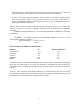
POSSIBLE TOOLS NEEDED FOR INSTALLATION If you decide to install your own stove, there are several hand tools you may need to do the job. If you do not already have them, they are readily available at most hardware stores.
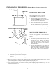
INSTALLATION PROCEDURE (Without Direct or Positive Connect Kit) POSITIONING THE HEATER When positioning the heater, the following conditions MUST be met! (See Figure 2.) 1. The front of the damper opening must be positioned BEHIND the rear edge of the lintel to ensure proper draft. (See Figure 2.) 2. The vertical plane of the fireplace front must fall BEHIND the side cold air vent on top of the unit. (In other words, it is possible to have the heater too far in as well as not far enough.) 3.
7. Next using high heat silicone or furnace cement, run heavy bead of caulking around where panels meet the stove. (See Figure 4.) 8. Using the brass trim provided with kit, place side brass trim (with straight edge down) over each outer edge of side trim panel. Next place top brass trim over top trim panel. All 45º corners should match. If not, trim to fit with a metal cutting blade. 9. Slide the unit back into the fireplace.
FINAL CHECK 1. Recheck the specified clearances. 2. Remove all foreign material from the firebox area. 3. Open the primary air draft. NOTE: Plug the power cord into a 115 VAC outlet. Route the cord to prevent damage to the cord insulation from heat and sharp objects. Keep the cord out of the way of traffic to prevent damage caused by tripping, etc. 4. Place crumpled pieces of newspaper in the stove. Light it and close the doors. Ensure that the stove draws properly through the primary draft.
SECTION III PRE-FAB ZERO CLEARANCE INSERT INSTALLATION The Model 18 may be installed into any UL listed prefabricated fireplace that is large enough to accept it. MINIMUM CLEARANCES Except for “NOTE(S)”, FOLLOW MASONRY INSTALLATION CLEARANCES FOUND IN YOUR OPERATIONS MANUAL. INSTALLATION PREPARATION Pre-Fab Zero Clearance Fireplace 1. Locate furniture and other materials away from the front of the fireplace to allow free access to the fireplace. 2.
NOTE: DO NOT BLOCK ANY EXISTING LOUVERS OR VENT ON THE EXISTING PREFAB WITH ANY TRIM PANELS FOR THE MODEL 18. NOTE: If the Pre-Fab Zero Clearance Fireplace is not equipped With HT-2100 degree UL Listed pipe, a UL-1777 Liner must be Installed the the Full Length of the chimney, and attached to the Flue Exit of the Insert. NOTE: If the Pre-Fab Zero Clearance Fireplace is equipped with HT-2100 degree UL Listed pipe, one of the two following methods must be met: HEATER INSTALLATION 1.
MINIMUM CLEARANCE TO COMBUSTIBLES INCREASER FIGURE A PACK TIGHT WITH CERAMIC WOOL (DO NOT USE GLASS WOOL) 6” FLEX PIPE OR ADJUSTABLE ELBOW FIGURE B 13
2. To complete this installation, follow the basic masonry fireplace trim kit instructions EXCEPT: The trim kit may have to be cut down in size so as not to block any cooling vents/chambers of the Zero Clearance Fireplace. 3. To complete methods 1 and 2, position the heater into the ZC Fireplace and center the flue exit under the connection. 4. Slide the connector (or slip connector) down into the flue exit of the heater approximately 3/8".
SECTION IV RESIDENTIAL FREESTANDING INSTALLATION MINIMUM CLEARANCE TO COMBUSTIBLE MATERIAL PREPARING THE STOVE FOR INSTALLATION 1. Remove the protective plastic wrapping from the unit. 2. Inspect the unit for any obvious physical damage. NOTE: Plug the power cord into a 115 VAC outlet. Route the cord to prevent damage to the cord insulation, from heat and sharp objects. Keep the cord out of the way of traffic to prevent damage caused by tripping, etc. 3.
ALTERNATE FLOOR PROTECTORS MATERIAL Floor protector must be 3/8" minimum thickness non-combustible material or equivalent. With the floor protector or hearth extension material specified as one layer of 2" thick brick with a K* factor of 5.0, you may use alternate materials as long as the K factor(s) is calculated as follows: FORMULA: Required thickness = (K of alternate material/K of millboard) x (thickness of millboard) EXAMPLE: An alternate inorganic non-combustible millboard with a K of .
CLEARANCES FOR MODEL -18 RESIDENTIAL FREESTANDING INSTALLATION MINIMUM CLEARANCES TO COMBUSTIBLES NOTE: All clearances are to combustibles without low clearance shields and using single wall pipe and minimum floor protector. Clearances above may be reduced. Follow NFPA-211 codes if available or follow instructions on next page. W JA CE NT G 45 DEGREES MODEL MODEL 18 D D FRONT A E A 10" B 14" C 15" D 9" E 16" F 8" * Floor Protector at rear needed for through-the-wall exit only.
Chimney Ceiling Exits: These models are designed for connection to: (1) Simpson Duravent - Dura Black (2) Metal Fab (3) Ameritec - BSR NOTE: This room heater must be converted to (1) a chimney complying with the requirements for Type HT chimneys in the Standard for chimneys, Factory-Built, Residential, Type and Building Heating Appliance, UL 103, or (2) a code approved masonry chimney with a flue liner.
CEILING SUPPORT BOX SINGLE WALL PIPE Figure 6 Figure 7 B. WALL EXIT INTO METAL TEE-BOX 1. Mark the plumb line on the wall directly behind the center of the heater. (See Figure 7.) NOTE: When using 24# ga. minimum blue or black steel pipe, maintain 18" between pipe and ceiling. 2. Place the vertical portion of the heater pipe and the elbow in position and project a point onto the plumb line level with the center of the elbow.
3. Measure up so there will be at least 1/4" rise per foot of horizontal connector pipe, maintaining clearances to the ceiling as noted in Figure 7. This will give you the center of the hole for the chimney penetration. 4. After locating the center of the penetration, install the tee box and chimney as per the chimney manufacturer's specifications. 5. Connect the chimney collar to the tee-box using #24 ga. minimum blued or black steel connector pipe. DO NOT use galvanized pipe.
equivalent material that will resist corrosion, softening, or cracking from flue gases at temperatures up to 1800º F. NOTE: In addition, a connector to a masonry chimney shall extend through the wall to the inner face or liner but not beyond, and shall be firmly cemented to masonry. Exception: A thimble may be used to facilitate removal of the chimney connector for cleaning, in which case the thimble shall be permanently cemented in place with hightemperature cement. 2.
CEILING SUPPORT BOX SINGLE WALL PIPE OPTIONAL CHIMNEY CONNECTOR Figure 9 Close Clearance Installation using: (1) 6" Simpson Dura-Vent single wall chimney connector (Dura Black) and 6" Simpson Dura-Vent 2100 Deg HT (Type DP) chimney or (2) 6" Metal Fab Type single wall connector and 6" Metal Fab 2100 HT chimney or (3) Ameritec. For Minimum Clearances see page 17. ALCOVE INSTALLATION CLEARANCES Must use 6" single wall connector and 6" Type HT pipe listed for Close Clearance reduction listed in this manual.
ALCOVE INSTALLATION CLEARANCES NOTE: Clearances to be used with double wall pipe and low clearance shield. B C F A DOUBLE WALL PIPE G E I H D FIGURE 10 MODEL 18 A 8" B 10" C 12" D 7" E 16" F 8" * Floor Protector at rear needed for through-the-wall exit only.
FINAL CHECK 1. Recheck the specified clearances. 2. Remove all foreign material from the firebox area. 3. Open the primary air draft. NOTE: Plug the power cord into a 115 VAC outlet. Route the cord to prevent damage to the cord insulation from heat and sharp objects. Keep the cord out of the way of traffic to prevent damage caused by tripping, etc. 4. Place crumpled pieces of newspaper in the stove. Light it and close the doors. Ensure that the stove draws properly through the primary draft. 5.
SECTION V FREESTANDING MOBILE HOME INSTALLATION NOTE: See page 26 for clearances for Mobile Home. FLOOR PROTECTION Floor protector must be 3/8" minimum thickness non-combustible material or equivalent. With the floor protector or hearth extension material specified as one layer of 2" thick brick with a K* factor of 5.
CLEARANCES FOR MODEL -18 RESIDENTIAL FREESTANDING INSTALLATION AND MOBILE HOME INSTALLATIONS MINIMUM CLEARANCES TO COMBUSTIBLES USING SINGLE WALL PIPE AND LOW CLEARANCE SHIELDS B C G F A D D E Figure 11 MODEL 18 A B C D E F G 8" 10" 12" 7" 16" 8" 8" NOTE: All clearances are to combustibles using single wall pipe and all optional low clearance shields and minimum floor protector. *Floor protector at rear needed for through-the-wall exit only.
INSTALLATION OF CLOSE CLEARANCE SHIELDS (Optional) Take rear close clearance shield and align it with the pre-punched holes in the rear skin of stove. Insert self-tapping screws through the shields into the stove. Next, take side shield (end with the holes goes toward the rear of the stove) and insert the screws through the holes in the side shield into the rear shield. Before tightening the screws insert the front end of the shield behind the side angle on the front side of the stove.
TOOLS FOR INSTALLATION Drop cloth 3/32" Metal drill bit 5/16" magnetic socket chuck adapter, 5/16" wrench (box or socket) or adjustable wrench Jigsaw with masonry, metal and wood blades WARNING: DO NOT INSTALL IN A SLEEPING ROOM. PREPARING THE HEATER FOR INSTALLATION 1. Remove the protective plastic wrapping from the unit. 2. Inspect the unit for any obvious physical damage. NOTE: Plug the power cord into a 115 VAC outlet. Route the cord to prevent damage to the cord insulation from heat and sharp objects.
6. Check that the pedestal stand is still aligned with the marks. Mark the outside air opening of the stand on the pad. 7. Next, mark the center line of the outside air opening. Set stand aside. 8. Next, cut a 4 1/4" diameter hole in the pad and continue through the floor. CAUTION THE STRUCTURAL INTEGRITY OF THE MOBILE HOME FLOOR MUST BE MAINTAINED. (MOVE OPENING AND/OR REPOSITION HEATER LOCATION IF NECESSARY). 9.
RAIN CAP RAIN CAP 24" min. (610 mm) 24" min. (610 mm) 36" TYP. FLASHING 36" TYP. FLASHING RADIATION SHIELD RADIATION SHIELD 20 FT. MAX. OUTSIDE AIR DUCT THROUGH FLOOR WHEN MOBLE HOME IS NOT UNDERPENNED OUTSIDE AIR DUCT THROUGH UNDERPENNED Figure 12 For ceiling exit using close clearance listed chimney 1. Suspend a plumb bob from the ceiling above the unit so that the weight is hanging in the center of the flue exit. (A small weight on a string will serve as a plumb bob.
(b) Chimney pipe height is at least 2 feet higher than any part of the roof within 10 feet of the chimney. (See Figure 12.) 4. Next, install a New Buck Corporation chimney connector to the flue of the heater or use 3 “ELL” brackets and secure to the top of the heater and pipe. 5. Using single wall chimney connector, connect the heater to the chimney by following manufacturer's installation instructions exactly. (See Figure 13.
4. Place crumpled pieces of newspaper in the stove. Light it and close the doors. Ensure that the stove draws properly through the primary draft. 5. Check for smoke leaks around the doors. 6. Open the doors and check for smoke escaping from the front of the stove. Smoking usually indicates a defective or poorly positioned chimney. Some chimneys with a marginal draft can be preheated by lighting newspaper and holding it near the open damper with a poker or fire tong.
The chimney and chimney connector should be inspected once every two months. Any buildup of soot should be removed to prevent the risk of a chimney fire. To remove chimney or chimney connector: Remove screws or fasteners. Remove pipe and clean with steel brush. Replace chimney or chimney connector, and replace screws and/or fasteners. CAUTION NEVER USE GASOLINE, GASOLINE TYPE LANTERN FUEL, KEROSENE, CHARCOAL LIGHTER FLUID OR SIMILAR LIQUIDS TO START OR "FRESHEN UP" A FIRE IN THE HEATER.
BUILDING A FIRE 1. Open the door. 2. Open the primary air control located on right side of stove under hearth. To close push all the way in. To open pull all the way out. Use air setting, located on primary air handle, for low, low-medium, medium-high, and high. 3. Twist two pieces of non-colored newspaper into a roll and place them on the floor of the firebox. 4. This model is not designed for the use of grates, andirons or other methods of supporting the fuel. 5.
SECTION VIII ROOM AIR BLOWER OPERATION Your heater is equipped with a room air blower. For operation and wiring see below. NOTE: Plug the power cord into a 115 VAC outlet. Route the cord to prevent damage to the cord insulation from heat and sharp objects. Keep the cord out of the way of traffic to prevent damage caused by tripping, etc.
SECTION IX TROUBLESHOOTING PROBLEM Sluggish heater POSSIBLE CAUSE SOLUTION Obstruction in chimney Check for and remove obstruction Improperly sealed trim kit or direct connect kit (a) Check trim kit gasketing seal to fireplace and gasket as necessary to seal unit. Check gasket under front bottom of stove if needed. (b) Check seal if direct connect and correct. Wet or unseasoned wood being burned. Burn dry seasoned wood. Poor chimney draft Improper chimney height or wrong size flue is being used.
PROBLEM POSSIBLE CAUSE SOLUTION High fuel consumption Improper regulation of draft or inlet air ( a) Close inlet air control as much as possible to maintain desired heat output. (b) Check gaskets, reinstall fiberglass gasketing around doors and glass as necessary Improper door fitting Check door gasket, check adjustment of door latch, check door hinges. Gusts of Wind a) Smoke shelf in chimney is filled with creosote & ash b) Chimney may need wind diverter. Raise chimney for better draft.
EPA COMPLIANCE STATUS The Model 18 heater meets the U.S. Environmental Protection Agency’s Emission limits for wood heaters sold after July 1, 1992. Under specific conditions this heater has been shown to deliver heat at rates ranging from approximately 10,000 to 45,000 BTU/Hr for the Model 18. MODEL 18 WOOD STOVE 32 1 11 34 4 5 13 16 20 7 14 33 15 18 30 & 31 29 8 27 16 21 26 3 19 12 10 6 24 25 23 9 22 1. Secondary air tubes 2. Blower Air Chamber 3. Primary air control 4.
REPLACEMENT PARTS FOR THE MODEL 18 Description Part No. 1. Air Control Bar 2. Door Handle Assembly 3. Door Roping 3/4" 4. Glass Gasket 5. Inside Motor Plate Blanket 6. Outdoor Motor Plate Blanket 7. Door Gold 8. Door Black 9. Thermostat 110 disc 10. Power Cord 11. Strain Relief 12. Motor - Non-cat 13. Firebrick 14. Glass 15. Glass, Bay side 16. Glass clip 17. 1/4" plain washer-pltd. 18. Cotter Pin 19. Door Hinges 20. 5/16" LK washer-gr5 21. Spring Handle 22. “U” Drive Screw 5/16" x 1/2" 23.
NEW BUCK CORPORATION (NBC) "LIMITED WARRANTY" FOR THE BUCK STOVE PLEASE READ THIS WARRANTY CAREFULLY PRODUCTS COVERED This warranty covers the new Buck Stove heating unit, so long as it is owned by the original purchaser, including optional and standard accessories purchased at the same time, subject to terms, limitations, and conditions herein set out. PRODUCTS NOT COVERED This warranty does not cover the following: Glass; Refractory material such as refractory cement or firebrick; Gaskets.
If for any reason you are dissatisfied with the suggested procedures, you may contact us in writing at: New Buck Corporation P. O. Box 69 Spruce Pine, NC 28777 CONDITIONS AND EXCLUSIONS A. Replacement of parts may be in the form of new or fully reconditioned parts, at NBC's option. B. There is no other express warranty. All implied warranties of merchantability and fitness for use are limited to the duration of the Express Warranty. C.