
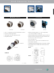
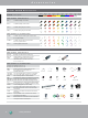
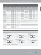
XLR Part Number Guide

setting standards
40
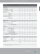
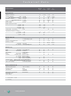
Technical Data Ordering Information
Number of contacts 3 - 5 3 - 7 (6*) 5 - 10 3 / 3
Contact resistance XLR:
≤
6 mΩ
≤
10 mΩ
≤
10 mΩ
1/4"& switching contacts**:
≤
20 mΩ
-
-
≤
10 mΩ
Insulation resistance - initial:
>
10 GΩ
- after damp heat test:
>
1 GΩ
>
500 mΩ
Dielectric strength 1.5 kV dc
Rated voltage 50 V ac
Rated current per contact
3 pole: 6 A
16 A 16 A - 3 A
4 pole: 6 A
10 A 10 A - -
5, 6 pole: 3 A
7.5 A 7.5 A - -
7 pole: 5 A
-
- -
Combo XLR + Jack contact 7.5 A
- -
Capacitance between contacts
3 pole:
≤
7 pF
≤
4 pF
≤
4 pF
≤
2 pF
≤
2 pF
4, 5, 6 pole:
≤
7 pF
- -
7 pole:
≤
9 pF - - -
Lifetime
>
1`000 mating cycles
Insertion / withdrawal force
≤
20 N 25 N
Retention method
- standard: latch lock
(XLR) (XLR)
- "0" Version:
≥
20 N separating force
25 N 25 N
Insert Polyamide PA 6.6 30% GR
Shell Zinc diecast ZnAI4Cu1
- -
Shell plating gal Ni or black Cr
Ni - -
Ring Zinc diecast ZnAI4Cu1
- - - -
Contacts - female 3 pole: Bronze CuSn6
-
4 – 5 pole: Bronze CuSn6
- - - -
4 – 7 pole: Brass CuZn39Pb3
-
- -
- male: Brass CuZn35Pb2
- -
Contact surface gal 0.2 µm AuCo over 2 µm NiP15 (Tribor
®
) - -
gal 2 µm Ag or gal 0.2 µm Au hard alloy over 2 µm Ni Au - -
Latch lock & spring Ck 67 steel, treated -
*... P Series male 3 – 6 pole
**... if existing
Operating temperature -30 °C to +80 °C
Protection class IP 40 IP 65
Flammability UL 94 HB
UL 94 V-0 - - - -
Solderability complies with IEC 68-2-20
Mounting screw - - A A
Color coding - - - -
Specification MPR-HD P Combo A
Series Series Series Combo
Electrical
Mechanical
Material
Environmental