7 inch LCD/Keyboard Rack Kit Installation guide for the RFT-17 Line into a 4-post 19-inch EIA cabinet Table of Contents Hardware Installation… …………………………………………………………………… Connecting your LCD/Keyboard………………………………………………………… Operating your LCD/Keyboard..…………………………………………………………. Navigating the Menu.………………………………………………………………………. On-Screen Display (OSD) Menus………………………………………………………… Trouble Shooting Bad Image Quality…………………………………………………… Specifications……………………………………………………………………………….
17 inch LCD/Keyboard Rack Kit Installation Guide Page 2 of 14
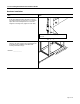
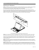
17 inch LCD/Keyboard Rack Kit Installation Guide Hardware Installation Step Detail 1. Determine the vertical location for the LCD/keyboard in the rack. Mark the location with tape or a pencil. This product requires one rack unit (1 ¾”) of vertical space. Mount the LCD/keyboard at a convenient height for an average user. (Approx 44” from floor) Ensure the bottom of the kit is properly positioned in a rack unit 2. Measure the distance from the front rack mounting rail to the rear rack mounting rail.
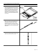
17 inch LCD/Keyboard Rack Kit Installation Guide Step 3. Remove the slides from the tray assembly. The slides come shipped attached to the tray assembly, the outer slide members must be removed to be properly installed into the rack. To remove the outer slide members, fully extend both slides to the open position. Once extended unlock the outer slide members by lifting up on the left side latch and pressing down on the right slide latch. The outer slide member can now be removed from the tray assembly.
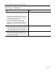
17 inch LCD/Keyboard Rack Kit Installation Guide Step Detail 6. Attach the left slide rail assembly to the rack mounting rail by using (6) #10-32 x ½” screws for the front and rear slide mounting brackets. Repeat for the right slide rail assembly. 7. Tighten the screws that attach the rear slide mount bracket to the outer slide member. (From step 4) (4X) 8. Extend the slides from the rack. 9. Install the LCD/keyboard assembly into the rack.
17 inch LCD/Keyboard Rack Kit Installation Guide Connecting your LCD/Keyboard Step Detail ! Note: Before connecting the LCD monitor/keyboard to a KVM or Sun System, all systems should be turned off. 1. The keyboard and trackball’s design allows its use with most Sun systems. The LCD-17-8P com es with an 8pin Din keyboard connector, while the LCD-17-USB comes with a USB style connector. 2. The monitor uses a standard HD-15 male video connector.
17 inch LCD/Keyboard Rack Kit Installation Guide Operating your LCD/Keyboard NOTE: It is important to ensure that the monitor is connected and powered on prior to powering up the connected Sun system. By powering up the Sun System last it will allow the frame buffer within the Sun system to communicate with the LCD monitor and self configure to the correct settings. After the unit has been installed and all cables connected, power on the LCD monitor by lifting the head unit.
17 inch LCD/Keyboard Rack Kit Installation Guide press the Menu button at the rear of the LCD panel twice, which will select the Display Mode menu. Note that deviations of a fraction of a hertz in the displayed refresh rate are not significant. NOTE: If the monitor self configures to any other resolution, it is likely that the frame buffer has been explicitly configured to display that particular resolution.
17 inch LCD/Keyboard Rack Kit Installation Guide Navigating the Menu (on some models the menu panel may be located on the back of the LCD) The LCD monitor will auto-adjust at start-up. Although not required, you can make numerous adjustments to your monitor using the on-screen menu. To access the OSD (On-Screen Display) menu Press the MENU button located at the top of the LCD monitor. The table below describes various function controls of the LCD Monitor.
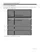
17 inch LCD/Keyboard Rack Kit Installation Guide On-Screen Display (OSD) Menus The menu pages can be displayed by pressing the Menu button. Not all menu functions can be adjusted.
17 inch LCD/Keyboard Rack Kit Installation Guide Trouble Shooting Bad Image Quality Image quality problems (blurry characters, distorted images, etc) are usually caused by one of the following: The frame buffer is running at the wrong resolution for the LCD monitor: The monitor optimally runs at a resolution of 1280x1024x60Hz unless the frame buffer cannot provide this resolution. To display the monitor resolution, press the Menu Button at the top of the LCD twice.
17 inch LCD/Keyboard Rack Kit Installation Guide technology that has no flicker in normal operation, and it is never influenced by the refresh rate. When the monitor is run at refresh rates higher than 60Hz there is processing overhead, which can cause a number of performance issues, included degraded image quality and greater tendency for interference. The first and foremost recommended vertical refresh rate for the LCD Monitor is 60Hz (1280x1024@60Hz).
17 inch LCD/Keyboard Rack Kit Installation Guide Specifications Frame Buffer Compatibility PGX, PGX32, PGX64, XVR Expert3D-Lite, Expert3D Creator/Creator3D (Series 2 and 3) Creator/Creator3D (Series 1) 1280x1024 resolution at 60Hz 1280x1024 resolution at 60Hz 1280x1024 resolution at 60Hz 1152x900 resolution at 66Hz General Compatibility Keyboard Rack Systems Sun Serial Interface or Sun USB Interface 4 Post EIA All systems with a qualified frame buffer and a Sun serial or USB keyboard.
17 inch LCD/Keyboard Rack Kit Installation Guide Warranty NLS warrants to the original retail purchaser that this product is and will be free from defects in materials and workmanship for a period of 24 months from the date of purchase. During the warranty period, purchaser must promptly call NLS (805-389-5435) to log any such defects in materials and workmanship. The warranty is void under the following conditions: 1. If non-NLS approved cabling is attached to the product.