
Manual

12
EN
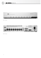
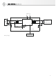
AES42 IN
Eight 3-pin XLR inputs for connecting digital mi-
crophones.
AES/EBU OUT
25-pin sub-D connectors with Yamaha and Tascam
pinout for the AES/EBU output signal.
The AES/EBU signal includes 2 standard audio
channels.
The distribution of the audio data of adjacent
mono microphone channels between the audio
channels of the corresponding AES/EBU output
signal is as follows:
• Channel 1 AES/EBU OUT
Left: microphone 1
Right: microphone 2
• Channel 2 AES/EBU OUT
Left: microphone 3
Right: microphone 4
• Channel 3 AES/EBU OUT
Left: microphone 5
Right: microphone 6
• Channel 4 AES/EBU OUT
Left: microphone 7
Right: microphone 8
Digital stereo microphones are supported at odd-
numbered AES42 microphone inputs only. In this
case the audio data of the microphones are routed
to the left and right channels of the corresponding
AES/EBU output.
ADAT OUT
Connector (Toslink) for the optical transmission
of the 8 microphone channels at 44.1 kHz or
48 kHz.
GN OUT
The RJ 45 connector for serial transmission of
the 8 microphone channels employs a special
data format developed by Neumann. This signal
will be used by Neumann multi-channel audio
interfaces in the future for converting to formats
such as Ethersound, MADI, etc. This special data
format permits very simple processing for word
clock frequencies of up to 192 kHz. The GN OUT
simultaneously supplies power for the Neumann
multi-channel audio interfaces. The result is a
very cost-eff ective system solution with extensive
functionality and fl exibility.
CONTROL BUS (RS 485)
RJ 45 ports for connecting a computer (PC or
Mac). Standard Ethernet (patch) cables are used
(Shielded Twisted Pair – STP or Unshielded Twist-
ed Pair – UTP).
Data transfer is performed via an RS 485 interface
with an additional power-out pin, for the optional
supply of an external control device.
Attention: The RJ 45 ports of the DMI-8 must
not be connected to an Ethernet.
The two RJ 45 ports are connected in parallel, in
order to permit multiple DMI devices to be cas-
caded and controlled by a single computer.
The DMI-8 is connected to the normally avail-
able USB port of a PC or Mac. The Neumann USB/
RS 485 converter (not included) is required for
this purpose. This permits the plug-and-play ca-
pability of existing USB ports to be combined with
the much greater cable lengths (of 100 m or more)
that are possible with an RS 485 connection.
ID [device address]
A coding switch permits setting of the device ad-
dress. If multiple DMI devices are cascaded and
controlled by a single computer, they must have
diff erent device addresses (IDs).
Attention: The ID is detected only during the pow-
er-up process. After the ID is changed, the power
supply must therefore be interrupted briefl y and
then turned back on again.
Please see the RCS control software operating
manual for information concerning the mode of
operation and assignment of device addresses.
USER PORT
The user port permits the direct control of the
microphone functions Mute, Light 1 and Light 2
(selected via RCS) by means of external switch
contacts or logic signals.
The assignments of the 9 pins are as follows (low-
active):
pin 1 channel 1
pin 2: channel 2
pin 3: channel 3
pin 4: channel 4
pin 5: ground
pin 6: channel 5