
Installation Instructions


12 © 2015 UTC Fire & Security Americas Corporation, Inc. All rights reserved.
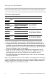
Wiring the NX-595E
Caution: Remove all power (AC and battery) to the NetworX security system
before proceeding. Failing to do so could result in possible damage to the product.
Terminal descriptions
Terminal
Description
1
Pos
Panel
Bus
Positive terminal
2
Com
Common terminal
3
Data
Data terminal on the NetworX panel
14
Z1
Additional
Zones
1
st
/ 3
rd
Zone
3.3K = Single EOLs
3.7K = Low zones
6.9K = High zones
15
Com
Common (-) return for Zone
loop
16
Z2
2
nd
/ 4
th
Zone
20
NC1
Relay 1
Normally closed
This relay can be controlled
from the UltraSync application
21
C1
Common
22
NO1
Normally open
23
NC2
Relay 2
Normally closed
This relay can be controlled
from the UltraSync application
24
C2
Common
25
NO2
Normally open
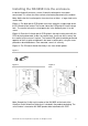
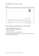
1. Connect the NX-595E's terminals POS, COM & DATA to the NetworX bus.
2. Connect one end of an Ethernet cable to the RJ45/Ethernet connector on the
NX-595E. Connect the other end of the Ethernet cable to an available Ethernet
port on the Internet router. The router should automatically assign the NX-595E
module an IP address when it is powered up.
3. If you are utilizing the output relay or additional zone functionality of the NX-
595E, connect the wiring to the appropriate terminals. Additional instructions
regarding output relay and zone functionality are included this manual.
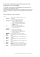
4. Re-connect the power to the NetworX security system. You are now ready to
configure the NX-595E.
Note: In the unlikely event that the Internet router is not configured to automatically
assign an IP address, you will have to manually assign an IP address and network
settings in the NX-595E. Instructions to manually assign the network settings are
included in Appendix 1 at the end of this manual.