
Installation Instructions


© 2015 UTC Fire & Security Americas Corporation, Inc. All rights reserved. 11
Installing the NX-595E into the enclosure
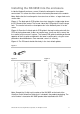
Inside the NetworX enclosure, several 2-holed insertion points have been
constructed. This allows for either vertical or horizontal placement of the module.
Note: Notice that the insertion points have two sizes of holes - a larger hole and a
smaller hole.
Figure 1: The black plastic PCB guides have slots along the straight edge where
the PC Board will be seated. The curved side of the PCB guide fits into the larger
hole. The smaller hole on the raised protrusion in the NetworX panel is for the
screw.
Figure 2: Place the first black plastic PCB guide in the top insertion point with the
PCB slot facing downward. It does not require force. Insert one of the screws into
the smaller hole to secure it in place. The second PCB guide should be positioned
opposite of the first guide and placed in the lower insertion point, using the same
procedures described above. Once mounted, screw it in securely.
Figure 3: The PC board should slide freely in the slots of both guides.
Figure 1
Figure 2
Figure 3
Note: Record the 12 digit serial number of the NX-595E on the back of the
UltraSync Quick Reference Guide that is included in the product packaging. The
serial number is located on NX-595E product label attached to the PCB.