NetworX™ Series NX-148E LCD Keypad Installation and Setup Includes models NX-148E, NX-148E-CF, and NX-148E-CF-W
© 2005 GE Security All rights reserved. These instructions do not purport to cover all details or variations in equipment nor to provide every possible contingency to be met during installation, operation, and maintenance. If further information is desired or if particular problems arise that are not covered sufficiently for the purchaser’s purpose, the matter should be referred to GE Security, USA.
Table of Contents 1. ENTERING THE PROGRAM MODE....................................................................................................... 4 2. SELECTING THE MODULE TO PROGRAM ........................................................................................ 4 3. PROGRAMMING A LOCATION .............................................................................................................. 4 3A. NUMERICAL DATA........................................................................
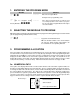
1. ENTERING THE PROGRAM MODE ACTION RESULT [Go To Factory Default is Enters the Program Mode. Prompts for the programming code. Program Code ] If the "Go To Program Code" is valid, the LCD screen will prompt for the device address to program. You are now in the Program Mode and ready to select the module. 2. SELECTING THE MODULE TO PROGRAM Tip: All modules connected to the NX control panel are programmed through the keypad.
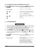
3b. BINARY DATA The top line of the display will show the current location number on the left and the segment number on the right. The data will be displayed on the bottom line with the numbers 1-8 in the first 8 characters. If the number appears, this binary switch is on. If a minus sign (-) appears where the number should be, this switch is off. Toggle numbers on or off using the corresponding number digit (1 to toggle 1; 8 to toggle 8). When the numbers are in the desired state, enter .
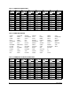
Table 3-1 ENGLISH CHARACTERS No. No. 00 01 12 13 02 03 04 05 06 07 08 09 10 11 A B C D E F G H I J K 14 15 16 17 18 19 20 21 22 23 No. L M N O P Q R S T U V W 24 25 26 27 28 29 30 31 32 33 34 35 No. 36 37 X Y Z 0 1 2 3 4 5 6 7 8 38 39 40 41 42 43 44 45 46 47 No. 9 a b c d e f g h I j k 48 49 50 51 52 53 54 55 56 57 58 59 No. l m n o p q r s t u v w 60 61 62 63 64 65 66 67 68 69 70 71 No. 72 73 x y z ! " # $ % & ' ( ) 74 75 76 77 78 79 80 81 82 83 No. r + , .
Table 3-4 AMERICAN SPANISH LIBRARY ABAJO CONTACTO EXTERIOR JARDIN PRINCIPAL SOTANO ALARMA CRISTAL FACHADA LABORATORIO PUERTA TALLER ALMACEN DESPACHO FUEGO LATERAL RECEPCION TECHO ARRIBA DETECTOR GARAJE LAVABO RECIBIDOR TERRAZA AVERIA DISPARO GERENCIA MAGNETICO SABOTAJE TIENDA AZOTEA DOBLE TECHNOLOGIA GOLPE OFICINA SALA TRASERO BARRERA DORMITORIO HABITACION PANICO SALIDA VALLA CAJA FUERTE EMERGENCIA HUMO PARED SALON VENTANA CLARABOYA ENTRADA INFORMATICA PASI
6. PROGRAMMING THE KEYPADS This section describes how to program the address and partition of each keypad, as well as the available options. The address of the keypad is important because this is how the panel supervises the keypads. FACTORY DEFAULTS: Master Code: when using a 4-digit code, or for a 6-digit code Go To Program code: when using a 4-digit code, or for a 6-digit code 6a. USING THE FUNCTION MENU ACTION RESULT Accesses the Function menu.
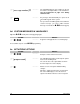
6b. ADJUSTING THE VIEW & BRIGHTNESS OF THE LCD ACTION RESULT Prompts to “Please Enter Your Code". [master code] Prompts to raise or lower the View angle. or Using the scroll keys to the right of the LCD, you can raise or lower the viewing angle of the text. Advances to the Brightness option. or Use the scroll keys again to adjust to desired brightness. Exits this mode. Prompts to brighten or dim the LCD lighting.
[message number] # The LCD will display the zone number on the top line and the description will be on the bottom line. Use the instructions on page 5 for editing character data. Any changes will automatically be copied to all other LCD keypads in the system. EXIT If you desire an LCD keypad to have a different custom message, you must enable Custom function (pg 10) Message Lock under the 6d. CUSTOM MESSAGES IN LANGUAGE 2 Tip: Exit mode prior to changing languages.
OPT 1 2 3 4 5 6 7 8 9 10 11 12 KEYPAD FEATURES NOT USED SILENT KEYPAD? Enable Silent Keypad Option. If enabled, only the entry/exit and sounder chime are silenced. DING DONG CHIME? Enable Ding Dong Sound for Chime. If off, chime will be a single tone. (Refer to NX control panel installation manual, location 40) 5 SEC. SILENCE? Enable Keypress Silence Option. Silences the pulsing keypad sounder for 5 seconds when a key is pressed. ARMED ZONE INFO? Enable Armed Zone Information.
7. KEYPAD FUNCTIONS 7a. READING THE EVENT LOG The control panel has an event log that can be retrieved using a master code. This log contains a listing of the last 185 events along with date, time, and partition where the event occurred. ACTION RESULT Prompts to “Please Enter Your Code". [master code] Shows the most recent event. Views the events from newest to oldest. Views the events from oldest to newest.
DISPLAY Open Close Exit Err Rec Close Autotest Start Prog End Prog Start Dnld End Dnld Cancel Gnd Flt Man Test Re-exit Output Trip Data Lost Walk-test End Test Cross-Trip Expansion Event Partial Arm Listen In Service Start Service End Code Entry First Open Last Close Sprnklr Clock Set RF Jammed CleanMe DESCRIPTION Open - Reports user number, date, time and partition of opening. Close - Reports user number, date, time and partition of closing.
7c. SET SYSTEM TIME AND DATE ACTION RESULT [master code] Displays date and time with the current hour flashing. or Scroll to select the proper hour. Advances to the selection for the minutes. Prompts to “Please Enter Your Code". Repeat the last two steps until the entire time and date is set. 7d. ADJUST KEYPAD TONE ACTION RESULT Prompts to use the scroll keys (right of the display) to raise or lower the tone.
7f. VIEW ALARM MEMORY ACTION RESULT Displays the zone descriptions. or Displays the alarm memory list in sequential order by zone number. # Exits the mode. 7g. TEST FUNCTION ACTION RESULT Test will be performed as programmed. If the siren test is performed, enter a user code to silence the siren. 7h. DISPLAY TEST FUNCTION ACTION RESULT All display pixels and LED indicators will flash. Press any key to end test. 7i.
7j. HOUSE CODES FOR X-10 DEVICES When used in conjunction with an X-10 output device such as the NetworX NX-507E, NX-508E, NX-534E or NX-540E, this menu allows the installer to program the specific X-10 unit and house codes for the ten X-10 devices for this keypad. ACTION RESULT Prompts to “Please Enter Your Code". [program code] Displays Light number and Unit Code. [X-10 unit code] Prompts for the House Code of the device.
[new user code] Prompts for a user number. Repeat steps 3 and 4 if another user code needs to be programmed. Keypad will beep 3 times if code is rejected. # Exits and saves data. while display is prompting for a user number. 7m. ASSIGNING AUTHORITY LEVEL You must have authority to the partition you wish to add or remove from another person’s authority. ACTION RESULT Prompts “Please Enter Your Code". [master code] Prompts for a user number.
7n. RESET FUNCTION The system must be disarmed to perform this function. ACTION RESULT The smoke detectors, zone troubles, and zone tampers have now been reset. If the keypad begins beeping, the reset did not execute properly. Enter your code to silence the keypad. Wait a few minutes and repeat step 2 to attempt another reset. 7o. OTHER FUNCTIONS (while system is disarmed) Causes the control to do a callback for a download.
8. PARTITIONED SYSTEMS OPERATION 8a. MASTER MODE The LCD keypad can be programmed to operate all the system partitions simultaneously. To set the multi-partition mode, use the function as described on page 10, and answer "YES" to the question "Master keypad?" 8b. “TEMPORARY” MASTER MODE Press [user code] to temporarily access the Master Mode. The keypad will revert back to its assigned partition 60 seconds after a key press or 10 seconds without a key press. Press # to exit. 8c.
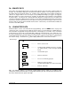
8d. DISPLAYS IN THE PARTITIONING MASTER MODE ARMED AND READY STATUS The LCD screen will display the Armed and Ready status of ALL eight (8) partitions if any or all of the areas is armed or not ready. Refer to the following examples: All 8 areas are Ready, and areas 3 and 5 are disarmed. Ready Armed 12345678 12-4-678 Flashing number on the ready line = area is ready to be Force Armed. Flashing number on the armed line = area is armed Instant.
Operating Individual Areas in the Multi-Partition Mode Enter a code that is a valid arm/disarm code for the area you wish to operate. 12-45-78 Disarm --3-56-- Arm º º Only the areas authorized by this user code will appear. To toggle between the armed and disarmed states on an individual area, press [Area Number]. To operate an individual area, enter the number of the partition you wish to operate. The LCD keypad will now operate as a single area keypad.
Control Fail to Comm. Control The control attempted to communicate a message to the Central Station, but was unsuccessful. A short to ground has been detected on a control circuit. Ground Fault Control Your system has lost total power and needs the clock reset. Loss of Time Control The main power to your system is not on. Power Trouble Control Low Battery An auxiliary reporting device has failed to communicate, i.e. NX-580E, NX-582E, etc. Expansion Aux Comm The standby battery is low.
Zone Low Battery, Press Zone A wireless device has a low battery. Press to identify the zone. A wireless or multiplexed zone device is not reporting to the control. Press to identify the zone. Lost, Press r Zone A zone is experiencing some form of trouble (probably wiring). Press to identify the zone. Trouble, Press r DEVICE NUMBERS FOR REPORTING The following table provides the device numbers that will be reported for trouble conditions.
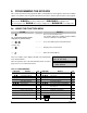
11. SPECIFICATIONS OPERATING POWER 12 VDC Regulated Supplied by NX control panel or NX-320E OPERATING TEMPERATURE 32 to 120 degrees F CURRENT DRAW 110 mA Maximum 75 mA without Sounder LCD KEYPAD DIMENSIONS 6.4" Wide 5.3" High 1.0" Deep SHIPPING WEIGHT 2 lbs. COMPATIBLE NETWORX CONTROL PANELS NX-4 NX-4V2 Main Outside the US Main Fax NX-6 NX-6V2 800-727-2339 903-845-6941 903-845-6811 NX-148E INSTALLATION MANUAL NX148EIC05 REV.