GE Security NetworX Series TM NX-1248E LCD keypad User manual
TABLE OF CONTENTS TABLE OF CONTENTS ..................................................................................................................................................................2 INTRODUCTION ...........................................................................................................................................................................4 GLOSSARY OF TERMS ............................................................................................................
APPENDIX A – EVENT LOG........................................................................................................................................................25 APPENDIX B – REFERENCE TABLES .........................................................................................................................................
INTRODUCTION This manual is furnished to help you understand your security system and become proficient in its operation. All users of your security system should read and follow the instructions in this booklet and, if possible, practice on the keypad control while your professional installer is on site. Failure to do so could result in the security system not working properly. Please keep this booklet in an accessible location for the life of the security system.
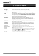
GLOSSARY OF TERMS Abort Delay Authority Level Central Station Chime Feature Codes Duress Code Forced Arming Function Code Group Bypass Instant/Delay Master Code Partitioned System Perimeter Quick Arm User Code NX-1248E User manual An option that allows a delay in reporting to the central station. The level of access an individual has when using an alarm panel. The location where alarm data is sent during an alarm report.
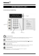
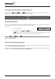
KEYPAD DISPLAY & LED’S Understanding the lighted keys Up & down scroll keys 4 Function keys Programmable emergency activation keys Numeric code entry keys or AWAY Lighted key The AWAY lighted key is “on” when the system is armed. The AWAY lighted key is “off” when it is disarmed. The AWAY lighted key will flash when there has been an alarm during the previous arm cycle. or STAY Lighted key The STAY lighted key is “on” when the system is armed.
Instant Message The LCD display will read “Instant“ when the entry/exit door(s) have no delay. (See “Arming System in Stay Mode”) The doors can be changed from instant to delay (toggled) by pressing the [STAY] key when the system is armed. EMERGENCY ACTIVATION KEYS NOTES: You must hold these keys for 2 seconds to activate these functions. Your system may not be programmed for these activation keys. You should press these keys only in an emergency situation that requires response by emergency personnel.
KEYPAD FUNCTIONS Arming your system in the “AWAY” mode AWAY is utilized when the user is going away from the premise and wants the interior protected. Listed below are the steps to arm in the AWAY Mode: Step 1 Close all protected doors and windows. • The System Ready message will be displayed when all protected zones and sensors are secure NOTE: If any zones are bypassed, a sensor in that zone can be violated without affecting the ready light.
Arming your system in the “STAY mode” STAY is utilized when the user is inside the premise and wants protection around the perimeter. The steps to arm in the STAY Mode are as follows: Step 1 Close all protected doors and windows. • The System Ready message will be displayed when all protected zones and sensors are secure. NOTE: If any zones are bypassed, a sensor in that zone can be violated without affecting the ready light. • The security system will not arm if the System Not Ready message is displayed.
Changing modes while system armed (optional) [AWAY], [STAY], or [NIGHT] key will change to the corresponding mode. Once the Double pressing the AWAY mode is entered, the system must be disarmed to change modes. IMPORTANT! The instant message needs to be off if you plan on re-entering the building, otherwise you will create an alarm. You may re-initiate an entry/exit delay by pressing the [STAY] key again. The instant message will go out.
Bypassing zones If you wish to bypass one or more zones, this must be done while the system is in the disarmed state. If the zone is not known, refer to Procedure 2. Procedure #1: If you know the number of the zone to bypass, use the following steps: Step 1 Press the [BYPASS] key. Step 2 When the LCD prompts for a code (optional, if programmed), enter your user code. Step 3 The bypass light flashes. Step 4 Enter the zone number (each time 2 digits) of the zone(s) that must be bypassed.
Unbypassing [BYPASS] key. Step 1 Press the Step 2 When the LCD prompts for a code (optional, if programmed), enter your user code. Step 3 The bypass light flashes. Step 4 Enter the zone number (each time 2 digits) of the zone(s) that must be unbypassed. (Example: to bypass zones 4 en 5, press [0][4][0][5].) Step 5 Press the Step 6 The bypass light will stop flashing. [BYPASS] key again. NOTE: All zones will automatically be unbypassed each time the system is disarmed.
ASSIGNING USER CODE AUTHORITY LEVELS Assign authority levels to users by following the steps below. Assign user codes before assigning authority levels. Your system must be in the disarmed state to change user code authority levels. Step 1 Press [r]-[6]. Step 2 Enter a [“Master Arm/Disarm Code”]. NOTE: Someone changing the authority of another person can only add or remove partition authorization for partitions to which they have access.
OTHER KEYPAD FUNCTIONS User menu The LCD keypads /displays have a bilingual user’s interface. As a result, you can simply select a user’s function on the menu. You can consult the menu by entering the [r] key. To select a user’s function following steps have to be performed. Step 1 Enter the [r] key. The display will now begin scrolling through a list of functions and the corresponding numbers associated with those functions. ex.
View zone status Step 1 Enter the [r] key followed by the [ ] key. The LCD Screen will display the zone status. Step 2 Use the up and down scroll keys [ ][ ] to browse through the descriptions. The LCD Screen will display the list of all zones in sequential order by zone number. Step 3 Press [#] to exit this function. Setting the keypad tone Step 1 Press the [r] key followed by the [0] key. Keypad is now in the “Adjust Tone” mode.
Step 4 The LCD display will prompt you for a new phone number. Enter the phone number Note : Step 5 Enter phone num. EEEEEEEEEEEEEEEE - empty location are shown as a “E”. In order to delete a number, you just program all “E”’s. This is done with the [bypass] key. - with the “*” key, the cursor can be shifted to the right without changing the telephone number. When finished, press the [#] key to leave this program mode.
Change languages This function allows you to switch between the two languages programmed in your keypad. NOTE: You must exit any other function mode before attempting to change languages. Step 1 Press [r] [4] [9]. The LCD display switches to the other language. Step 2 To switch back to the other language, only step 1 has to be repeated. Detector reset function This function is used to reset Smoke Detectors and Zone Troubles. Your system must be Disarmed to use the Reset function.
Adjusting the view/brightness of the LCD Step 1 Enter [r][9][1]. The LCD Screen will prompt for a code. Step 2 Enter [master code]. The LCD will now prompt you to raise or lower the view. Step 3 Using the [r][9][1]scroll keys to the right of the LCD, you can raise the text or lower the text. Step 4 To advance to the Brightness option, press [r]. the LCD lighting. Step 5 Use the [ ][ ] scroll keys again to adjust to desired brightness. Step 6 When completed, exit by pressing [r].
PARTITIONED SYSTEMS OPERATION This system is “ multi-partitioned “ not partitioned If your system is multi-partitioned and the keypad resides in one partition, your keypad will provide the status of the zones in your partitioning by using the screen messages described earlier in this manual. The Master Mode of operation (if programmed by your installer) allows you to access any partitioning (providing your code is authorized) within the system and perform functions in other partitions.
Displays in partitioning master mode ARMED AND READY STATUS The LCD screen will display the Armed and Ready status of ALL eight (8) partitions if any or all of the areas is armed or not ready. Armed Ready 1234-678 12345678 System Ready Type code to arm This display is reflecting all 8 areas are Ready, and Area 5 is disarmed. NOTE: If a number is flashing on the armed line, that area is armed Instant. If a number is flashing on the ready line, that area is ready to be Force Armed.
OPERATING INDIVIDUAL AREAS IN THE MULTI-PARTITION MODE Enter a code that is a valid arm/disarm code for the area you wish to operate. The following display will appear on the LCD screen. 12-4- - 78 - -3- 56- - Disarm Arm Only the areas authorized by this code will appear. To toggle between the armed and disarmed states of an individual area, press [r] [Area number]. To operate an individual area, enter the number of the partition you wish to operate.
KEYPAD CONTROL TONES (BEEPS) A sounder is built into the keypad and may sound for any of the following reasons: • Beeps for all keypresses. • Sounds a continuous tone during the Entry delay time. • Pulses when a day zone is violated while the system is disarmed. • Pulses when a FIRE zone has a trouble condition. • Pulses when the armed status changes and the AC power is off. • Beeps 3 times for trying to arm with the “READY” light off, if “FORCE ARMING” has not been selected.
SERVICE DISPLAY The following message will be displayed periodically if the security system requires service. Call your service provider promptly if this message is observed. Service Required Type r2 for help If you see this display, press [r] followed by the [2] key. One or more of the following fault messages will be displayed. Use the [ ][ ] scroll keys to browse through them. To exit the service messages, press [#]-[#]. Control Over-current A short circuit of a control’s power supply has occurred.
Expander Box tamper Expansion Trouble A box containing an expansion device has been opened. An expansion device or keypad is not reporting to the control panel. Expansion Siren trouble Open circuit has occurred on the bell or siren circuit of the expander. Expansion RF Jammed A radio receiver is being jammed (Not applicable to all controls.) Zone Tamper, Press r A zone is tampered. Press [r] to identify the tampered zone. Zone Low Batt, Press r A wireless device has a low battery.
APPENDIX A – EVENT LOG NOTE: Your system may not have all of the features listed in this table.
DISPLAY DESCRIPTION Last Close Sprnklr Clock Set RF Jammed CleanMe Last Close Sprinkler Clock Set RF Jammed CleanMe Reports when the last partition is armed. Instant sprinkler supervisory report Clock has been reset. A wireless expansion module is jammed A smoke detector requires cleaning. APPENDIX B – REFERENCE TABLES IMPORTANT These reference tables on the following pages need to be completed by your installer.
Programmed functions: Abort delay Battery test Cancel alarm Change partitions (LED) Chime Communicator test Manual fire alarm Manual medical alarm Manual panic alarm Forced arming Group bypass Quick arm Re-Exit Service Light/Message enabled Siren test Zone descriptions : Zone 1 Zone 2 Zone 3 Zone 4 Zone 5 Zone 6 Zone 7 Zone 8 Zone 9 Zone 10 Zone 11 Zone 12 Zone 13 Zone 14 Zone 15 Zone 16 Zone 17 Zone 18 Zone 19 Zone 20 Zone 21 Zone 22 Zone 23 Zone 24 Zone 25 Zone 26 Zone 27 Zone 28 Zone 29 Zone 30 Zone 31
Zone 41 Zone 124 Zone 125 Zone 126 Zone 127 Zone 128 Zone 129 Zone 130 Zone 131 Zone 132 Zone 133 Zone 134 Zone 135 Zone 136 Zone 137 Zone 138 Zone 139 Zone 140 Zone 141 Zone 142 Zone 143 Zone 144 Zone 145 Zone 146 NX-1248E User manual Zone 82 Zone 147 Zone 148 Zone 149 Zone 150 Zone 151 Zone 152 Zone 153 Zone 154 Zone 155 Zone 156 Zone 157 Zone 158 Zone 159 Zone 160 Zone 161 Zone 162 Zone 163 Zone 164 Zone 165 Zone 166 Zone 167 Zone 168 Zone 169 Page 28 Zone 123 Zone 170 Zone 171 Zone 172 Zone 173 Zone
www.gesecurity.net EMEA Distribution is a division of GE Security EMEA bvba COPYRIGHT ©2005 © GE Security EMEA bvba. All rights reserved. GE Security EMEA bvba grants the right to reprint this manual for internal use only. GE Security EMEA bvba reserves the right to change information without notice.