NTI R 1275 Danner Dr Tel:330-562-7070 NETWORK TECHNOLOGIES Aurora, OH 44202 Fax:330-562-1999 www.networktechinc.
TRADEMARK UNIMUX is a trademark of Network Technologies Inc in the U.S. and other countries COPYRIGHT Copyright © 2000-2007 by Network Technologies Inc. All rights reserved. No part of this publication may be reproduced, stored in a retrieval system, or transmitted, in any form or by any means, electronic, mechanical, photocopying, recording, or otherwise, without the prior written consent of Network Technologies Inc, 1275 Danner Drive, Aurora, Ohio 44202.
TABLE OF CONTENTS INTRODUCTION............................................................................................................................................................. 1 MATERIALS .................................................................................................................................................................... 1 DEFINITIONS......................................................................................................................................
Translation Capabilities .......................................................................................................................................... 29 Translation Tables .................................................................................................................................................. 29 International Sun Keyboards ..................................................................................................................................... 30 CASCADING .
NTI UNIMUX SERIES USB KVM SWITCH INTRODUCTION The UNIMUX-USBV-x (formerly referred to as KEEMUX-USBV-xU) USB KVM switch (UNIMUX) allows access to any Windows, MAC, or SUN USB CPUs from one monitor, USB keyboard and USB mouse (up to 32 CPUs as a single switch or 512 CPUs when cascaded). Internal microprocessor circuitry allows all USB CPUs to be booted simultaneously without keyboard error. Port selection is accomplished by front panel push buttons or commands typed on the keyboard.
NTI UNIMUX SERIES USB KVM SWITCH DEFINITIONS • • USB Composite Device USB Hub • CPU • • Input Device System A USB device that contains multiple endpoints each representing input devices that cannot be separated (i.e. a keyboard with a built-in mouse) A USB device that allows one or more USB input devices to plug in to the USB. The hub has exactly one upstream port with one or more downstream ports which input devices connect to Enclosure that contains the operating system and processor (i.e.
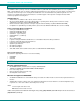
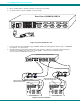
NTI UNIMUX SERIES USB KVM SWITCH F E A T U R E S A N D F U N C T IO N S F r o n t V ie w o f U N IM U X -U S B V -8 1 D a is y O u t N T I D a is y In R N e t w o r k T e c h n o lo g ie s In c R S 2 3 2 O n 8 1 C a s c a d e O ff 1 S c a n 3 7 2 3 5 4 4 8 T M 8 1 2 U N IM U X B ro a d c a s t C o m m a n d 6 7 8 5 9 6 R e a r V ie w 1 0 1 1 C P U 8 C P U 7 C P U 6 C P U 5 C P U 4 C P U 3 C P U 2 C P U 1 o f U N IM U X -U S B V -8 1 2 U S B D E V IC E S R S 2 3
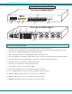
NTI UNIMUX SERIES USB KVM SWITCH RACKMOUNTING INSTRUCTIONS This NTI switch was designed to be mounted to a rack or to set on a desktop. It includes rackmount ears to make attachment to a rack easy, and rubber feet to be applied to the bottom of the case if it will instead sit on a flat surface. If this will sit on a flat surface, simply apply the rubber feet to the bottom of the case in each of the 4 corners. To Mount to a Rack 1.
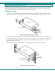
NTI UNIMUX SERIES USB KVM SWITCH INSTALLATION 1. 2. It is not necessary to turn the CPUs or monitors OFF during this installation. Connect the cable from a VGA multi-scan monitor to the 15HD connector labeled “MONITOR” on the UNIMUX (See Fig. 3 below.
NTI UNIMUX SERIES USB KVM SWITCH 5. 6. When cascading switches, follow the instruction on page 29 for "Cascading". Connect the AC line cord to the UNIMUX. (See Fig. 5 below.
NTI UNIMUX SERIES USB KVM SWITCH Power-Up Sequence • • • The UNIMUX can be powered at any time. The CPUs can be powered at any time although if a CPU needs a keyboard and/or mouse at power-ON it should be powered after connecting to and powering-ON the UNIMUX. USB input devices (keyboard and mouse) can be hot plugged to and from the UNIMUX at any time.
NTI UNIMUX SERIES USB KVM SWITCH USING THE UNIMUX USB KVM SWITCH Once the UNIMUX is properly connected, the UNIMUX will enable a connection to be made between the CPUs attached to its VIDEO and CPU ports and the monitor and input devices attached to the MONITOR and DEVICES ports. The LEDs on the control panel of the UNIMUX will illuminate depending on which port (and corresponding CPU) is being connected to the monitor and input devices.
NTI UNIMUX SERIES USB KVM SWITCH MODES OF OPERATION Basic Command Mode In order to control the UNIMUX with the keyboard connected, Command Mode must be enabled. To enter Command Mode from the keyboard: (ACCENT ~ Ctrl Press KEY) + ` NOTE: IF THE OSD FEATURE HAS BEEN INSTALLED, PROCEED DIRECTLY TO “OPTIONAL OSD CONTROL” ON PAGE 12. If not, continue on this page.
NTI UNIMUX SERIES USB KVM SWITCH Broadcast Mode To activate Broadcast Mode press + from the Command Mode menu. Broadcast Mode enables the user to type characters to more computers simultaneously. From the Change Settings menu (see page 18) the user can edit the list of ports that receive data in Broadcast Mode.
NTI UNIMUX SERIES USB KVM SWITCH Mice and Trackballs with MACs The UNIMUX can be configured to enable full functionality between mice and trackballs having two or more buttons and USB MAC CPUs. By default, the ports on the UNIMUX are configured for use with WINDOWS and SUN CPUs and have no special translation for using multi-function mice and trackballs when a MAC CPU is connected.
NTI UNIMUX SERIES USB KVM SWITCH OSD CONTROL OSD superimposes a menu system on the user’s video screen with a list of all connected CPUs. OSD allows CPUs to be named (with up to 12-character names). OSD then allows selection of CPUs by that name. Connected CPUs can be listed by name or by port number. OSD Search Mode enables the user to type in the first few characters of the CPU's name and the OSD will locate it. Help screens assist with all OSD functions.
NTI UNIMUX SERIES USB KVM SWITCH User Login Mode User login mode requires a user to login with a user name and password from the list created by the administrator. This mode will also disable use of the front panel until the user logs in. Function: Adds a character to the user name/password Keystroke: A-Z 0-9 Removes previous character from the user name/password Submit user name/password Exit USER LOGIN and return to previous mode. This function is only available if security is not currently active.
NTI UNIMUX SERIES USB KVM SWITCH Administrator Password To change the administrator password press from the Administration Mode menu. The administrator is able to change the administrator password as needed (see Fig. 12). Two edit fields are available, one for password, the other for verify password. The password can be up to 13 characters in length. Note: The default password for the administrator is ADMINISTRATOR.
NTI UNIMUX SERIES USB KVM SWITCH Edit User To enter the Edit User mode press from the User Name List after selecting a user or an empty record. The Edit User mode (see Fig. 14) enables the administrator to: add a new user remove an existing user edit the settings for an existing user The Edit User mode contains three edit boxes and a check box list of up to 32 check boxes representing the User Access List (list of the CPU port(s) the user has access rights to).
NTI UNIMUX SERIES USB KVM SWITCH Alternate Command Hot Key To enable the administrator to assign a key in addition to the <`> (accent key) to use with to enter into OSD Command Mode, an Alternate Command Hot Key option is provided. The default factory setting for this option is <`> (disabling the option). To select an Alternate Command Hot Key, press from Administration Mode menu (page 13). A window will open and the administrator will be prompted to press a key.
NTI UNIMUX SERIES USB KVM SWITCH OSD Command Mode (Cont'd) Function: Keystroke: Selects a specific port Enters Search Mode and adds a character to search string and selects the CPU’s name that matches best. A-Z 0-9 Selects the first port on the switch Home Selects the last port on the switch End Display Help Menu F1 Update Configuration Exit OSD Command Mode (0-9) x - (0-9) x (Pxx would be P01, P02, etc.
NTI UNIMUX SERIES USB KVM SWITCH Scan Mode To activate Scan Mode press + from the Command Mode menu. When in Scan Mode the switch scans to each port with a CPU powered-ON. (The SCAN LED on the front panel will illuminate and remain ON while in Scan Mode.) The port with the CPU powered-ON remains active while in use until it becomes idle for the configured dwell time (default time-out period is 5 seconds) before switching to the next powered-ON CPU port.
NTI UNIMUX SERIES USB KVM SWITCH Change Settings To enter the Change Settings menu (see Fig. 18) press + from the Command Mode menu.
NTI UNIMUX SERIES USB KVM SWITCH Select Ports For Scan To Select Ports For Scanning, press from the Change Settings menu described on page 19. The Select Ports For Scan menu enables the user to select specific ports to be active in Scan Mode. Only the selected ports will be scanned in Scan Mode. A check list with all the port numbers preceded by a check-box will be displayed in the window.
NTI UNIMUX SERIES USB KVM SWITCH A check list with all the ports numbers preceded by a check-box will be displayed in the window. • unchecked box = the corresponding port is set as connected to a non-MAC CPU • checked box = the corresponding port is set as connected to a MAC CPU In order to change the status of a port, the administrator has to first select the port. The selected port is highlighted with a green bar. To select another port, the administrator can use the arrow keys or mouse movement.
NTI UNIMUX SERIES USB KVM SWITCH Maintenance Mode To enter Maintenance Mode press + from the Command Mode menu. Maintenance Mode enables a user to customize the On Screen Display to their requirements.
NTI UNIMUX SERIES USB KVM SWITCH Help Mode To enter Help Mode press the key from the Command Mode menu (on page 17). Help Mode displays a list of commands with a short explanation of their function. These lists are organized in pages for each mode (i.e. COMMAND, EDIT, and SEARCH). The following options enable the user to quickly obtain information on any command.
NTI UNIMUX SERIES USB KVM SWITCH RS232 CONTROL (Optional) RS232 enables the UNIMUX to be remotely controlled via RS232.
NTI UNIMUX SERIES USB KVM SWITCH Unit Address and Loop Back To allow multiple units to be controlled from a single CPU serial port, the RS232 control interface is designed to allow "daisy chaining" up to 15 units. By setting the appropriate RS232 dip switches, each unit can be given a unique address (1-15). Then the unit will only respond to commands on the bus if its address is embedded in the command. Use the table below to set the unit address.
NTI UNIMUX SERIES USB KVM SWITCH Command Protocol RS232 commands supported by the unit are defined below. All command strings should be terminated with a (carriage return). When a command is sent, the entire string is echoed back along with a response from the addressed unit as shown in the command definitions. All characters in the command string should be upper case, and all numbers below 10 should have a leading 0 (ex: 1 = 01).
NTI UNIMUX SERIES USB KVM SWITCH Matrix Switcher's Control Program For Windows 9X, NT, AND 2000 The Matrix Switcher's Control Program is an easy and powerful graphical program that controls NTI switches through an RS232 interface. The Matrix Switcher's Control Program is included on the CD packaged with the UNIMUX. The Matrix Switcher's Control Program is downloaded by clicking on the link "Download Matrix Switcher's Control Program". To install the Matrix Switcher's Control Program after downloading 1. 2.
NTI UNIMUX SERIES USB KVM SWITCH 9) Read Connection for Output/User - read what input is connected to the specified output a) Read Connection for Audio Output/User (only applicable to models with audio support) - read what input is connected to the specified output b) Read Mute Status and Volume for Audio Output/User (only applicable to models with audio support) - read the volume and the mute status of the specified output (Audio ports only) c) Read Unit Size - read the switch size (number of inputs
NTI UNIMUX SERIES USB KVM SWITCH MOUSE CLICK EQUIVALENTS To emulate a right button click using Apple 1 button mouse, hold down the Command key ( button. ) while pressing the mouse Note: Right mouse button emulation must be enabled (see Change Settings on page 19) for this to work. KEYBOARD FEATURES The keyboard configuration of each CPU is saved in the UNIMUX.
NTI UNIMUX SERIES USB KVM SWITCH E s c ~ N u m L o c k B a c k s p a c e ` T a b E n te r C a p s L o c k S h ift S h ift E n te r C trl A lt A lt C trl T y p ic a l 1 0 1 K e y b o a r d E s c F 1 F 2 F 3 F 4 F 5 F 6 F 7 F 8 F 9 F 1 0 F 1 1 ~ P r in t S c re e n S y s R q F 1 2 S c r o ll L o c k P a u s e B re a k N u m L o c k B a c k s p a c e ` T a b E n te r C a p s L o c k S h ift S h ift E n te r C trl A lt A lt C trl A p p lic a tio n K e y W in d o w s L o
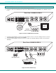
NTI UNIMUX SERIES USB KVM SWITCH CASCADING The UNIMUX-USBV-x USB KVM switch can be cascaded as shown in Fig. 31 below. Single user and multi-user UNIMUX switches may be connected downstream (see Figs.33 and 34). The first switch in a cascaded system is referred to as the "master", while all downstream switches are referred to as "slaves". The only additional hardware required to cascade switches is a set of device and monitor cables for each “SLAVE UNIT” (see MATERIALS on page 1).
NTI UNIMUX SERIES USB KVM SWITCH .
NTI UNIMUX SERIES USB KVM SWITCH M A S T E R C P U 8 C P U 7 C P U 6 C P U 5 C P U 4 C P U 3 C P U 2 C P U 1 (U N IM U X -U S B V -8 ) U S B D E V IC E S R S 2 3 8 M O N IT O R 4 7 V ID E O 3 6 2 5 V ID E O 1 2 N E T W O R K T E C H N O L O G IE S IN C 1 2 7 5 D a n n e r D r, A u ro ra , O H 4 4 2 0 2 T e l:3 3 0 -5 6 2 -7 0 7 0 w w w .n ti1 .
NTI UNIMUX SERIES USB KVM SWITCH Limitations ¾ ¾ ¾ If any switches made prior 9/22/04 are used as slaves, then all switches used as slaves must have the same number of CPU ports (all 4, 8, or 16 CPU ports). Up to 8 slaves may be connected to form a maximum system size of 152 ports (1x32 port master + 8x16 port slaves). Slaves must be added to the master in order (slave #1 to master’s port 1, slave #2 to master’s port 2, etc).