NTI R 1275 Danner Dr Tel:330-562-7070 NETWORK TECHNOLOGIES Aurora, OH 44202 Fax:330-562-1999 www.nti1.
TRADEMARK NODEMUX is a registered trademark of Network Technologies Inc in the U.S. and other countries COPYRIGHT Copyright © 2005 by Network Technologies Inc. All rights reserved. No part of this publication may be reproduced, stored in a retrieval system, or transmitted, in any form or by any means, electronic, mechanical, photocopying, recording, or otherwise, without the prior written consent of Network Technologies Inc, 1275 Danner Drive, Aurora, Ohio 44202.
TABLE OF CONTENTS INTRODUCTION ............................................................................................................................................................................... 1 MATERIALS ...................................................................................................................................................................................... 2 FEATURES AND FUNCTIONS .....................................................................................
TABLE OF FIGURES Figure 1- Secure rackmount ears to switch........................................................................................................................................ 4 Figure 2- Secure switch to rack ......................................................................................................................................................... 4 Figure 3- Dip-switch configuration ............................................................................................
NTI NODEMUX SERIES UNIVERSAL KVM SWITCH INTRODUCTION The NTI ST-xU UNIVERSAL KVM switch (NODEMUX) allows the user’s keyboard, monitor, and mouse to directly control any legacy PC, MAC, or SUN CPU connected to the switch (up to 32 CPUs as a single switch or 152 CPUs when switches are cascaded). These CPUs can be file servers, network managers, etc. Through the connection made by the NODEMUX, the user is able to control any one CPU connected to the system.
NTI NODEMUX SERIES UNIVERSAL KVM SWITCH MATERIALS Materials Supplied: • NTI ST-xU UNIVERSAL KVM Switch • IEC Line cord, country specific • CD with a pdf file of this manual Materials Not Supplied, but REQUIRED: • • • A set of 2 cables for each CPU being connected to the switch: • PS/2 CPU to Switch • SUN CPU to Switch • MAC CPU to Switch OR OR - VEXT-xx-MM for video interface VKTINT-xx-MM for keyboard and mouse interface VEXT-xx-MM for video interface 13W3M-15HDF (adapter for 13W3 to 15HD) SKTINT
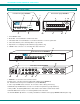
NTI NODEMUX SERIES UNIVERSAL KVM SWITCH FEATURES AND FUNCTIONS F r o n t V ie w R e a r V ie w o f le g a c y N O D E M U X 3 2 o f le g a c y N O D E M U X 1 6 7 12 R S 2 3 2 N T I R N e t w o r k T e c h n o lo g ie s In c V D O V I D E O - 4 3 5 6 7 8 O N 4 D E O 6 V I D E 5 7 I E O V 4 V I D D E O O 3 M V I D E O 2 I O N E O 1 T O F F 1 2 3 4 5 6 7 8 O N I R B ro a d c a s t C o m m a n d S c a n 2 V I D O 7 8 1 V I E 1 8 5 V D C 2 A C P U +
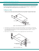
NTI NODEMUX SERIES UNIVERSAL KVM SWITCH RACKMOUNTING INSTRUCTIONS This NTI switch was designed to be mounted to a rack or to set on a desktop. It includes rackmount ears to make attachment to a rack easy, and rubber feet to be applied to the bottom of the case if it will instead sit on a flat surface. If this will sit on a flat surface, simply apply the rubber feet to the bottom of the case in each of the 4 corners. To Mount to a Rack 1.
NTI NODEMUX SERIES UNIVERSAL KVM SWITCH INSTALLATION 1. Turn OFF power to all CPUs that will be connected to the NODEMUX before connecting or disconnecting any cables to or from them. WARNING! DAMAGE MAY OCCUR TO THE CPU IF POWER IS NOT DISCONNECTED BEFORE CONNECTING OR ! DISCONNECTING CABLES. 2. Configure the dip-switches for the type of keyboard and mouse being used (see Fig. 3).
NTI NODEMUX SERIES UNIVERSAL KVM SWITCH 5. Connect the input devices (keyboard/mouse) to the port labeled DEVICES on the rear of the NODEMUX following one of the methods detailed below: • PS/2 keyboard and mouse- attach the 8-pin male end of a VKTINT-1 to the NODEMUX at the DEVICES port. The keyboard will plug into the 6-pin purple female connector with the keyboard symbol on it (see Fig. 5a), and the mouse will plug into the 6-pin green female connector with the mouse symbol on it (see Fig. 5b).
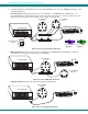
NTI NODEMUX SERIES UNIVERSAL KVM SWITCH 6. For each CPU: a. Connect the appropriate NTI keyboard cable (see the chart below) from the input devices port (keyboard/mouse) of the CPU to a CPU x port of the NODEMUX. Note the port’s number. (See Figs. 8-10.) b. Connect a VEXT-xx-MM video cable and video adapter, if needed (see the chart below), from the video port of the CPU to the VIDEO x port of the NODEMUX with the same port number as the keyboard (see Figs. 8-10).
NTI NODEMUX SERIES UNIVERSAL KVM SWITCH • SUN CPU- Connect a SUN CPU video port using a VEXT-xx-MM cable with a 13W3M-15HDF adapter between a VIDEO x port on the ST-xU and the CPU. Connect the SUN CPU keyboard/mouse port using an SKTINT-xx-MM between a CPU-x port on the ST-xU and the CPU. (See Fig. 10.
NTI NODEMUX SERIES UNIVERSAL KVM SWITCH 7. For Units with Touch-screen support (-TSO option) a. Connect the 15HD cable from the user monitor to the MONITOR port on the NODEMUX. b. Connect the 9D serial cable from the user monitor to the SERIAL port on the NODEMUX. c. Connect a keyboard and mouse using one of the methods described on page 5.
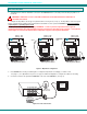
NTI NODEMUX SERIES UNIVERSAL KVM SWITCH CASCADING The NTI ST-xU Universal KVM switch can be expanded to access up to 152 CPUs by cascading multiple units together. Up to 8 SUN, MAC, or Universal switches can be connected into an ST-xU Universal KVM switch’s CPU ports, as shown in Fig. 14. The NODEMUX connected to the monitor and input devices must be configured as the “MASTER” unit. Any switches connected to the “MASTER” must be configured as “SLAVE” units.
NTI NODEMUX SERIES UNIVERSAL KVM SWITCH NOTES: • Port 1 of the Master Unit with Slave Unit #1 connected to it will function and be controlled as ports 1-4 for an ST4U (1-8 for an ST-8U, etc.) • Master Unit Port 2 with Slave Unit #2 connected will function and be controlled as the next sequential port numbers (5-8 for an ST-4U, 9-16 for an ST-8U, etc.). • Consecutive ports on the master used for locally connected CPU’s will function and be controlled as the next consecutive port number. (I.e.
NTI NODEMUX SERIES UNIVERSAL KVM SWITCH If to th C a d V e y P U d itio ID E O w ill p o r If ju s t in to p o rts b e c o n t re s p e c t n a & fu ts d ro iv 3 l 4 -P O R T s la v e s a r e c o C P U p o rts 3 & 4 , n c tio n a n d b e c o n tr o lle 9 -1 2 & 1 3 -1 6 r e s p e c tiv e - O R iv id u a l C P U 's a r e c o n n e c & 4 , th e y w ill fu n c tio n a lle d a s C P U p o r ts 9 & 1 0 e ly . M A S T E R n n e c te d U N IT (S T -4 U ) d a s ly .
NTI NODEMUX SERIES UNIVERSAL KVM SWITCH OPERATION Control over the CPUs attached to the NODEMUX is achieved through operation of the NODEMUX. Once the NODEMUX is properly connected, the NODEMUX will enable a connection to be made between the CPUs attached to its "VIDEO x" and "CPU x" ports and the keyboard, monitor, and mouse attached to the "MONITOR" and "DEVICES" ports.
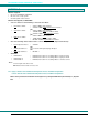
NTI NODEMUX SERIES UNIVERSAL KVM SWITCH Command Functions (Cont'd) Function: Keystroke: Toggle Scan Mode ON and OFF S Toggle Broadcast Mode ON and OFF B Sets scan time-out period for each port. Selects a specific port (The Scan Mode LED will toggle ON and OFF.) (The Broadcast Mode LED will toggle ON and OFF.) T P - (0-2) x (0-9) x (0-9) x - (0-9) x - (xxx from 002 to 255. ie. t002 would set the time-out period for 2 seconds) (0-9) x - (Pxx would be P01, P02, etc.
NTI NODEMUX SERIES UNIVERSAL KVM SWITCH Scan Mode When in Scan Mode the switch scans to each port with a CPU powered-ON. (The SCAN LED on the front panel will illuminate and remain ON while in Scan Mode. ) The port with the CPU powered-ON remains active while in use. When the switch becomes idle for the configured time-out period (default time out period is 5 seconds) the switch will connect to the next powered-ON CPU port. See Command Mode section on page 13 for configuring the scan time out period.
NTI NODEMUX SERIES UNIVERSAL KVM SWITCH When a standard user powers up the system a security screen may appear as setup by the administrator. The user will need to login to the system by following the instructions below for the USER LOGIN. If the user does not know the appropriate user name and password (setup by the administrator), contact the system administrator for this information.
NTI NODEMUX SERIES UNIVERSAL KVM SWITCH Switch Configuration Switch Configuration enables the administrator to configure the NODEMUX to be used as a stand alone switch or as one of the switches in a cascaded system. Switch Configuration is also used to setup the communication settings for RS232 communication with a remotely connected terminal through the RS232 port. For the Switch Configuration Mode menu, press from the Administration Mode menu (page 16). Be careful with this field.
NTI NODEMUX SERIES UNIVERSAL KVM SWITCH Note: After configuring an NODEMUX as a slave unit, when the power is cycled the slave NODEMUX will only be controllable through the master NODEMUX it is connected to. Direct OSD menu control of the slave unit will no longer be possible. In the event the setting is changed by mistake to "slave unit", to change it back to a "stand alone" switch, factory default settings must be restored via a terminal connected to the RS232 control port.
NTI NODEMUX SERIES UNIVERSAL KVM SWITCH User Name List The User Name List displays the list of users and provides control for adding new users, changing or assigning user passwords, and changing access rights for any given user. User names may be up to 12 characters long, may not contain spaces, and are not case sensitive. Passwords may be up to 15 characters long, may not contain spaces, and are case sensitive.
NTI NODEMUX SERIES UNIVERSAL KVM SWITCH The On Screen Display menu will automatically appear on the monitor in addition to illuminating the indicator LEDs on the KVM switch. This provides a visual way to control the NODEMUX using the keyboard, monitor, and mouse. With Touch Screen support (optional), the OSD menu can be entered by tapping 3 times on the monitor.
NTI NODEMUX SERIES UNIVERSAL KVM SWITCH Command Mode (Cont’d) Function: Keystroke: (0-2) x Sets scan time-out on each port Ctrl + T - Selects a specific port Ctrl + P - Selects the first port on the switch End Enters Search Mode and adds a character to search string and selects the CPU’s name that matches best. A-Z 0-9 Exit Command Mode (0-9) x (0-9) x - (0-9) x - (xxx from 002 to 255. ie. t002 would set the time-out period for 2 seconds) (Pxx would be P01, P02, etc.
NTI NODEMUX SERIES UNIVERSAL KVM SWITCH FYI: If switches are cascaded (such as that illustrated in Fig. 14 on page 10), it will be necessary to make note of which port each CPU is connected to on each slave KVM switch and which port each slave KVM switch is connected to on the master KVM switch.
NTI NODEMUX SERIES UNIVERSAL KVM SWITCH Selects the last port on the switch End Toggles between insert and overstrike Insert Erase current character Delete Erase previous character (The character either gets inserted and the remainder of the name gets shifted to the right, OR the current character gets overwritten.
NTI NODEMUX SERIES UNIVERSAL KVM SWITCH Maintenance Mode Maintenance Mode allows a user to customize the On Screen Display to their requirements Function: Keystroke: Reset all of the port names R Toggle between numeric and alphabetic listing of ports L Move On Screen Display (OSD) window up on monitor Move OSD window down on monitor Move OSD window to the right Move OSD window to the left Figure 26- Maintenance Mode Make OSD window taller T Make OSD window shorter S Change user password.
NTI NODEMUX SERIES UNIVERSAL KVM SWITCH Help Mode This mode displays a list of commands with a short explanation of their function. These lists are organized in pages for each mode (i.e. COMMAND, EDIT, SEARCH, and HELP). The following options allow the user to quickly obtain information on any command.
NTI NODEMUX SERIES UNIVERSAL KVM SWITCH Reset Default Values The default operating values of the connected touch screen monitor must be communicated to the NODEMUX before any connected CPUs are powered up. To reset default values, 1. Press + <`> (accent key) to enter Command Mode 2. Press + to enter Touch Maintenance Mode 3. Press to reset default values. The user will be prompted to with the question "Are You Sure?". Press to complete the procedure.
NTI NODEMUX SERIES UNIVERSAL KVM SWITCH RS232 CONTROL Rear View of ST-4U-RS NTI R NETWORK TECHNOLOGIES INCORPORATED 1275 Danner Drive, Aurora Ohio 44202 RS232 Connections and Configuration V I D E O OFF 1 2 3 45 6 7 8 ON 5VDC 2A - 330-562-7070 www.nti1.
NTI NODEMUX SERIES UNIVERSAL KVM SWITCH Unit Address and Loop Back To allow multiple units to be controlled from a single terminal port, the RS232 control interface is designed to allow "daisy chaining" up to 15 units. By setting the appropriate RS232 dip switches, each unit can be given a unique address (1-15). Then the unit will only respond to commands on the bus if its address is embedded in the command. Use the table below to set the unit address.
NTI NODEMUX SERIES UNIVERSAL KVM SWITCH Loop Back In order for an RS232 command and a response to the command to be viewed at the terminal screen, the NODEMUX must have its Loop Back feature enabled. More than one NODEMUX may be connected to a terminal at a time. To do so, a Matrix-Y-1 cable (available from NTI) must be used. (See Fig. 32). For each additional NODEMUX connected, another Matrix-Y-1 cable will be required.
NTI NODEMUX SERIES UNIVERSAL KVM SWITCH W ir in g S c h e m a tic o f M a tr ix -Y -1 c a b le 9 D M a le (U n it # 1 ) 9 D F e m a le (S o u rc e ) 9 D M a le (U n it # 2 ) 2 3 3 3 5 5 5 2 7 8 1 4 6 N o t c o n n e c te d to s o u rc e c o n n e c to r 2 J u m p e r J u m p e rs Figure 34- Pinout of Matrix-Y-1 cable Command Protocol Terminal control commands supported by the NODEMUX are defined below. Notes: • All commands should be terminated with an (ASCII 13) denoted by .
NTI NODEMUX SERIES UNIVERSAL KVM SWITCH CA - change all output channels FORMAT: RESPONSE: CA AA,XX CA = "change all outputs" command followed by at least one space AA = unit address XX = input /CPU to connect to all outputs/USERS * (command received and executed OK) ? (syntax or transmission error occurred) FYI: In this NODEMUX switch, this command will have the same effect as the CS command above.
NTI NODEMUX SERIES UNIVERSAL KVM SWITCH KEYBOARD-TO-CPU TRANSLATION The NTI NODEMUX enables the mixture of otherwise incompatible devices and CPUs to control each other. It accomplishes this by performing keyboard-to-CPU translations automatically (i.e. connect a MAC keyboard and mouse to a PS/2 type CPU). The chart below shows the key commands that will be recognized and translated for the different types of CPUs.
NTI NODEMUX SERIES UNIVERSAL KVM SWITCH Keyboard Replacement Should it be necessary to replace the keyboard of one platform with a keyboard of a different platform, the dip-switches will need to be re-configured accordingly. To do this; 1. Power-down the ST-xU by following the proper power-down sequence. That is, turn the CPUs OFF first, then the NTI switch. 2. Replace the keyboard. 3. Re-configure the switches (see Fig. 3 on page 5.) and then power up, following the proper power-up sequence.
NTI NODEMUX SERIES UNIVERSAL KVM SWITCH For models ST-xU (no OSD): 1. Make sure the ST-xU is completely disconnected from all CPU components. Be sure to unplug the ST-xU from the electrical outlet. 2. Remove the two philips-head screws from the underside of the ST-xU and set the ST-xU on a firm and flat surface, bottom down (see Fig. 37).
NTI NODEMUX SERIES UNIVERSAL KVM SWITCH 6. Carefully loosen the video board from the standoffs. With it loosened, grasp firmly the video board and front panel at the same time and slide the front panel up out of the slots in the plastic case that support it. Once the panel is clear of the case, pivot the assembly back approximately 1", just enough to expose the jumper block. (See Fig. 39.) Be careful not to dislodge the connection of the ribbon connecting the LED board to the digital board.
NTI NODEMUX SERIES UNIVERSAL KVM SWITCH NOTE: Before proceeding, it is important to discharge any static charge you may be carrying by touching any large metal object (away from the ST-xU-O). 4. Firmly grasp the front and rear panel and slide the entire assembly out of the lower case. 5. Remove the jack screws from the video and monitor connectors on the rear panel. Remove the rear panel from the assembly. 6. The uppermost board is the video board.
NTI NODEMUX SERIES UNIVERSAL KVM SWITCH Configuring the Jumper Block Once the jumper block is exposed, apply a jumper across the appropriate pins to disable the desired mode(s) according to the chart below. Pin Designation Mode KCMD Command Mode* BRDC Broadcast Mode SCAN Scan Mode *Note: Putting a jumper across pins KCMD to disable Command Mode will also disable Broadcast and Scan Modes. J U M P E R If th e u n it h a s a n L C D th is ju m p e r w ill b e h e r e .
NTI NODEMUX SERIES UNIVERSAL KVM SWITCH TROUBLESHOOTING PROBLEM: SOLUTION: Keyboard Errors Check cable connections on each CPU and the switch. NOTE: If the cable from a CPU’s keyboard port is disconnected from the NTI Universal KVM switch while power is ON, turn the power OFF to the CPU before plugging the cable back in. PROBLEM: SOLUTION: No Video • Check cable connections on each CPU and the switch. • Verify that the keyboard and video cables are connected from each CPU to matching ports.