
Installation and Operation Manual Audio/Video Matrix Switch SM-nXm-C5AV-LCD
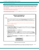
NTI VEEMUX AUDIO/VIDEO MATRIX SWITCH VIA CAT5
26
INTERCONNECTION CABLE WIRING METHOD
CAT5 Cable
The connection cable between the VEEMUX and XTENDEX remote and local units is terminated with RJ45 connectors and must
be wired according to the EIA/TIA 568 B industry standard. Wiring is as per the table and Fig. 32 below.
Pin Wire Color Pair Function
1 White/Orange 2 T
2 Orange 2 R
3 White/Green 3 T
4 Blue 1 R
5 White/Blue 1 T
6 Green 3 R
7 White/Brown 4 T
8Brown 4 R
Figure 32- View looking into RJ45 female
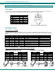
Null Modem Cables
Pinout of RS232 port on VEEMUX
The VEEMUX RS232 serial port is a DB-9M (male) connector configured as a DTE (data terminal equipment) port (like the 9 pin
serial port on a CPU). The RS232 port interface signals are listed below, including equivalent CCITT V.24 identification, and signal
direction:
DB-9M
pin #
Common
name
EIA
name
CCITT
name
Function Direction
1 DCD CF 109 Not used --
2 RxD BB 104 Receive Data Input
3 TxD BA 103 Transmit Data Output
4 DTR CD 108.2 Not used --
5 SG AB 102 Signal Ground –
6 DSR CC 107 Not used --
7 RTS CA 105 Request To Send Output
8 CTS CB 106 Clear To Send Input
9 RI CE 125 Not used --
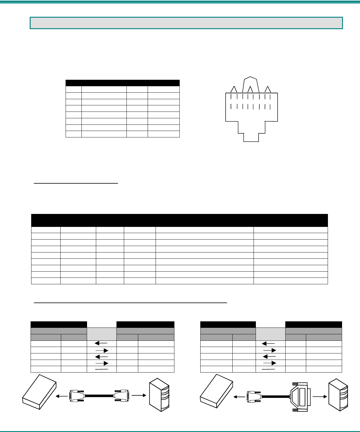
Pinouts for typical DTE to DTE null modem cable for CPU connection
VEEMUX (DTE) to 9 PIN DTE (PS2 or SUN) VEEMUX (DTE) to 25 PIN DTE (MAC)
VEEMUX PS/2 or SUN CPU VEEMUX MAC CPU
9 pin Signal 9 pin 9 pin Signal 25 pin
Function Pin # Direction Pin # Function Function Pin # Direction Pin # Function
RxD 2 3 TxD RxD 2 2 TxD
TxD 3 2 RxD TxD 3 3 RxD
CTS 8 7 RTS CTS 8 4 RTS
RTS 7 8 CTS RTS 7 5 CTS
SG 5 5 SG SG 5 7 SG
T
1
+
R
2
-
T
3
+
R
4
-
T
5
+
R
6
-
T
7
+
R
8
-
Pair 2
Pair 1
Pair 4
Pair 3
9 PIN
DTE
9 PIN
DTE
VEEMUX
PS/2 or SUN CPU
MAC CPU
25 PIN DTE
9 PIN
DTE
VEEMUX