NTI R 1275 Danner Dr Tel:330-562-7070 NETWORK TECHNOLOGIES Aurora, OH 44202 Fax:330-562-1999 www.networktechinc.
TRADEMARK VEEMUX is a registered trademark of Network Technologies Inc in the U.S. and other countries COPYRIGHT Copyright © 2003-2006 by Network Technologies Inc. All rights reserved. No part of this publication may be reproduced, stored in a retrieval system, or transmitted, in any form or by any means, electronic, mechanical, photocopying, recording, or otherwise, without the prior written consent of Network Technologies Inc, 1275 Danner Drive, Aurora, Ohio 44202.
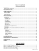
TABLE OF CONTENTS INTRODUCTION............................................................................................................................................................. 1 Materials ...................................................................................................................................................................... 1 Default User Name and Passwords ...............................................................................................................
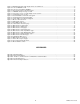
Figure 7- Maximum total CAT5 cable length cannot exceed 600 feet................................................................................................ 9 Figure 8- Connect VEEMUX to LAN .................................................................................................................................................. 9 Figure 9- Connect user terminal to VEEMUX ..............................................................................................................................
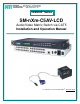
NTI VEEMUX AUDIO/VIDEO MATRIX SWITCH VIA CAT5 INTRODUCTION The SM-nXm-C5AV-LCD (VEEMUX) is an Audio/Video Matrix switch via CAT5 designed to work in conjunction with the NTI ST-C5VA-600 or ST-C5SVA-600 CAT5 Audio/Video Extender (XTENDEX). Up to 32 audio/video sources can be connected to the VEEMUX via XTENDEX Local Units (n), each accessible by up to 16 audio/video displays connected via XTENDEX Remote Units (m).
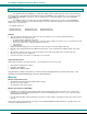
NTI VEEMUX AUDIO/VIDEO MATRIX SWITCH VIA CAT5 Default User Name and Passwords The default Telnet password is 16. admin (lower case letters only) . For instruction on using Telnet, see page The default Web Interface user name is Administrator (upper case letter for "A" only). The default Web Interface password is admin (lower case letters only). Interface, see page 17. For instruction on using the Web FEATURES AND FUNCTIONS VEEMUX Features and Functions 1.
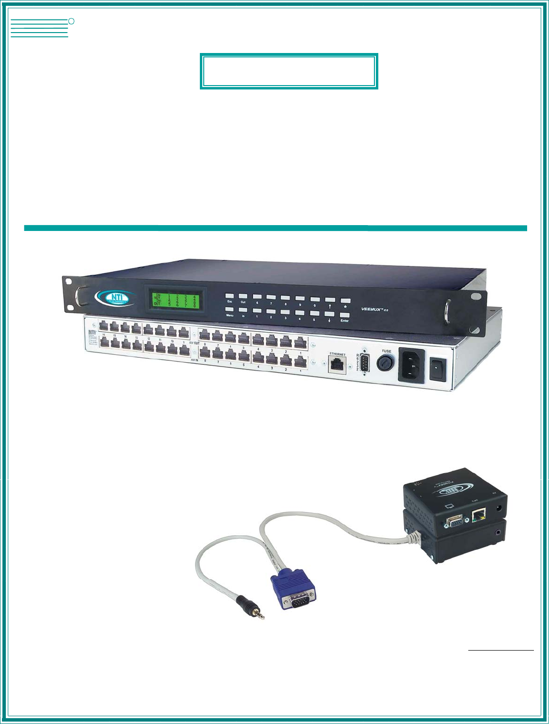
NTI VEEMUX AUDIO/VIDEO MATRIX SWITCH VIA CAT5 XTENDEX Features and Functions 1. Green LED- communication indicator- blinks when there is valid communication between the local and remote units. 2. Yellow LED- power indicator- illuminates when power has been supplied to the unit 3. Cat 5- RJ45 female- for connecting the CAT 5 cable 4. Video Connector- 15HD female- for connecting the local user's monitor 5. Audio Jack- 3.5mm stereo audio jack- for connecting to local speakers 6.
NTI VEEMUX AUDIO/VIDEO MATRIX SWITCH VIA CAT5 XTENDEX INSTALLATION (XTENDEX not included) Audio Compatibility • The audio input of the ST-C5VA-600 Audio/Video Extender is compatible with the following standard CPU audio outputs: • • • • Line out - typically lime green in color Speaker out- typically orange in color Headphone out- typically located on the CD-ROM (audio extension cable would be needed) The audio output of the ST-C5VA-600 Audio/Video Extender is compatible with self-powered stereo speake
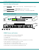
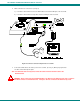
NTI VEEMUX AUDIO/VIDEO MATRIX SWITCH VIA CAT5 2. Make connections for a Local User (see Fig. 2) a) Connect the cable from the local user's VGA monitor to the female 15HD port on the Local Unit. b) Connect the cable from the local speakers into the 3.5mm jack on the local unit. Figure 2- Connect Local User Components to Local Unit 3. Connect the CAT5 cable to the “Cat 5” port on the Local Unit. (See Fig. 2.) When properly inserted the cable end should snap into place.
NTI VEEMUX AUDIO/VIDEO MATRIX SWITCH VIA CAT5 The Remote Unit 1. Position the Remote Unit such that the CAT5 cable, the monitor cable, speaker cable, and the AC adapter power connector can each reach the Remote Unit comfortably. 2. Connect the monitor cable to the female 15HD video connector on the Remote Unit. 3. Connect the speakers to the 3.5mm jack on the Remote Unit (see Fig. 3). Figure 3- Connect the Extended Components to the Remote Unit 4.
NTI VEEMUX AUDIO/VIDEO MATRIX SWITCH VIA CAT5 Plug-in and Boot Up 1. Plug the power cord from the monitor into the power outlet. 2. Connect each AC adapter power connector to the 9VDC ports on the Remote and Local Units. Make sure the power connectors go into each port all the way. Plug each AC adapter into a power outlet. The yellow LED on the RJ45 connector of both the Remote and Local Units should illuminate, indicating that a proper power connection has been made to them. (See Fig. 4.
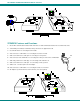
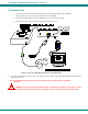
NTI VEEMUX AUDIO/VIDEO MATRIX SWITCH VIA CAT5 VEEMUX INSTALLATION 1. Connect an ST-C5VA-600 Local Unit to an audio/video source as described on pages 4-5. 2. Connect a CAT5 cable (wired as specified on page 26) between the ST-C5VA-600 Local Unit and VEEMUX connector "AV IN 1". Figure 5- Attach ST-C5VA-600 Local Unit to VEEMUX 3. Connect a CAT5 cable (wired as specified on page 26) between an ST-C5VA-600 Remote Unit and VEEMUX connector "AV OUT 1".
NTI VEEMUX AUDIO/VIDEO MATRIX SWITCH VIA CAT5 Note: This total length of CAT5 cable between the ST-C5VA-600 Remote and Local units cannot exceed 600 feet. (See Fig. 9) Figure 7- Maximum total CAT5 cable length cannot exceed 600 feet 6. To use the WEB Interface (page 15) , connect a CAT5 cable between the Local Network and the RJ45 connector on the VEEMUX labeled ETHERNET. (See Fig. 8) This cable should be wired straight through between two RJ45 connectors (pin 1 to pin 1, etc.
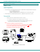
NTI VEEMUX AUDIO/VIDEO MATRIX SWITCH VIA CAT5 USING THE VEEMUX SWITCH The VEEMUX can be controlled by either of four methods: • • • • Using the keypad of the front panel interface Directly via an RS232 interface Remotely via web interface Remotely via telnet interface Front Panel Interface Overview On the front panel is an 18 push-button keypad and LCD that enable the user to operate the switch and change settings.(See Fig.
NTI VEEMUX AUDIO/VIDEO MATRIX SWITCH VIA CAT5 Keypad Control The front panel interface keypad and LCD enable the user to monitor switch status and route any user to any audio/video source (INPUT) on the switch. Along with the routing of the INPUTS to the user devices (OUTPUTS) the keypad and LCD allow the users to configure the RS-232 control interface and web server settings. The keypad buttons perform the following functions: Key Action ESC Cancel current action. 0–9 Used to enter numbers.
NTI VEEMUX AUDIO/VIDEO MATRIX SWITCH VIA CAT5 Set Serial Address When selecting this menu item, the display shows the current serial address and the user is prompted to introduce a new serial address. One or two digits can be entered followed by . The display will prompt if the address is successfully changed. Pressing will cancel this command. The serial address is used by the RS232 line to send commands. Valid addresses are between 1 and 99. The factory default address is 1.
NTI VEEMUX AUDIO/VIDEO MATRIX SWITCH VIA CAT5 Set Wserver Timeout When selecting this menu item, the display shows the current webserver timeout period and offers optional values to change it to. Figure 17- Wserver Timeout Period The currently selected value is highlighted. Move the highlight (using the arrow keys) to the desired timeout value and press to apply the value. An alternative method of selection is to press the number key that corresponds to the desired timeout value.
NTI VEEMUX AUDIO/VIDEO MATRIX SWITCH VIA CAT5 This function is particularly useful to determine if a lack of sound from speakers is due to failed speakers, or lack of audio signal through the VEEMUX. If no signal is seen in this display, check all connections between the audio source, the XTENDEX, and the respective Input port on the VEEMUX. Pressing again will return to the connections display.
NTI VEEMUX AUDIO/VIDEO MATRIX SWITCH VIA CAT5 Matrix Switcher's Control Program For Windows 9X, NT, 2000 and XP The Matrix Switcher's Control Program is an easy and powerful graphical program that controls NTI matrix switches through an RS232 interface from an attached PC. The Matrix Switcher's Control Program is included on the CD packaged with the VEEMUX. The Matrix Switcher's Control Program is downloaded by clicking on the link "Download Matrix Switcher's Control Program".
NTI VEEMUX AUDIO/VIDEO MATRIX SWITCH VIA CAT5 Telnet Interface The Telnet Interface enables the user to control the switch using telnet client through an Ethernet connection. The telnet server listens on port 2000. To access the telnet interface, using the current IP address type the following in a command shell: telnet 192.168.1.1 2000 The VEEMUX will prompt the user for a password. The user must enter the password followed by . The default factory password is "admin".
NTI VEEMUX AUDIO/VIDEO MATRIX SWITCH VIA CAT5 Web Interface A user may control the connections of the VEEMUX using a Web Interface via any web browser (see page 1 for web supported browsers). With the VEEMUX connected to a LAN through an Ethernet cable, a user can access the web interface controls inside the VEEMUX. FYI: To quickly locate a VEEMUX on the LAN and edit the IP address settings, use the Device Discovery Tool (page 25).
NTI VEEMUX AUDIO/VIDEO MATRIX SWITCH VIA CAT5 Switch Page Figure 22- Web interface Switch page The Switch page (above) displays the active connections (shown in orange) and enables the user to control the connections of the VEEMUX. Up to 10 different connection configurations can be saved and later recalled by any connection method. Note: Configuration 0 will be automatically loaded when the VEEMUX is powered up.
NTI VEEMUX AUDIO/VIDEO MATRIX SWITCH VIA CAT5 To save a configuraton, from the Stored Configurations user interface, use the drop-down list to select the desired slot (numbers 0-9) to save the active configuration into and press the Save button. Note: This will save the currently active configuration on the VEEMUX. If changes have been made in the web interface without first pressing the Submit button, those changes will not yet be part of the active configuration.
NTI VEEMUX AUDIO/VIDEO MATRIX SWITCH VIA CAT5 Setup Pages These settings enable the user to configure the VEEMUX web interface connection. • This change will take a few seconds and automatically redirect the user to the IP address specified. Note: Since the webserver will be restarting all active connections will be logged out. The Website Timeout option controls how long an inactive web connection will stay logged in. Any change to the Website Timeout configuration takes effect immediately.
NTI VEEMUX AUDIO/VIDEO MATRIX SWITCH VIA CAT5 Video Input Names The Video Input Names page enables the Administrator to change the name of the input ports displayed on the Switch page. To change a Video Input Name, enter the name of the input port for the desired port number, and press Save. Note: Only the changes to the input port directly to the left of the Save button will be saved. All other changes to input ports without pressing the port's respective Save button will be discarded.
NTI VEEMUX AUDIO/VIDEO MATRIX SWITCH VIA CAT5 Update Firmware Figure 27- Web interface Update Firmware page The Update Firmware page shows the current version of the firmware and enables the Administrator to update the firmware of the VEEMUX. WARNING: Failure to carefully follow these directions can permanently damage the VEEMUX. Please read these directions in full before continuing. Do not, under any circumstances, reset or power-down the VEEMUX while the firmware is being updated.
NTI VEEMUX AUDIO/VIDEO MATRIX SWITCH VIA CAT5 Change Password Page Figure 28- Web interface Password page Use this page to change the password for accessing the web interface. (This password is also used for the telnet interface.) Be sure to make note of the new password exactly as it is case sensitive. The password must be between 5 and 16 characters in length and can be alphabetical or numeric. Help Page This page explains the purpose of each of the other pages in the VEEMUX web interface.
NTI VEEMUX AUDIO/VIDEO MATRIX SWITCH VIA CAT5 Logout Page Figure 30- Web interface Logout page This page will enable the user to end the session and close the web interface connection. Click on the "Press Here to Continue Logout" button to exit the VEEMUX web interface. Note: The connection will timeout automatically after a preset period of inactivity, configurable on the Web Setup page.
NTI VEEMUX AUDIO/VIDEO MATRIX SWITCH VIA CAT5 DEVICE DISCOVERY TOOL In order to easily locate the VEEMUX on a network, or change network settings, the NTI Device Discovery Tool may be used. A link to the Discovery Tool is provided on the web page that appears when you insert the instruction manual CD into your CD ROM drive. Click on the link or browse the CD and click on the file discover.html . This will open your browser and display the Device Discovery Tool page.
NTI VEEMUX AUDIO/VIDEO MATRIX SWITCH VIA CAT5 INTERCONNECTION CABLE WIRING METHOD CAT5 Cable The connection cable between the VEEMUX and XTENDEX remote and local units is terminated with RJ45 connectors and must be wired according to the EIA/TIA 568 B industry standard. Wiring is as per the table and Fig. 32 below.
NTI VEEMUX AUDIO/VIDEO MATRIX SWITCH VIA CAT5 1 2 6 4 3 7 8 5 9 1 3 2 4 14 15 16 17 Mating Face of a 9D Male 5 6 18 19 7 8 20 21 9 10 11 12 13 22 23 24 25 Mating Face of DB25 Male TROUBLSHOOTING SOLUTION: No audio Check all connections and power to all devices.
NTI VEEMUX AUDIO/VIDEO MATRIX SWITCH VIA CAT5 Appendix C- Distances and Resolutions for CAT5/CAT5e and CAT6 Cables CABLE DISTANCE (feet) RESOLUTION CAT5/CAT5e (UTP) 600 1024x768 at 60Hz CAT5/CAT5e (UTP) 400 1280x1024 at 60Hz CAT5/CAT5e (UTP) 300 1600x1200 at 60Hz CAT5/CAT5e (UTP) 100 1920x1440 at 60Hz CAT6 (UTP) 300 1024x768 at 60Hz CAT6 (UTP) 200 1280x1024 at 60Hz CAT6 (UTP) 100 1920x1440 at 60Hz Appendix D- Product Dimensions CONFIGURATION SIZE (In.) WxDxH SM-8X8-C5VA-LCD 19x12x1.
NTI VEEMUX AUDIO/VIDEO MATRIX SWITCH VIA CAT5 Grounding These products have protective earth ground terminals and are built with full attention to consumer safety. There must be an uninterruptible safety earth ground between the main power source and the product's power cord or supplied power cord set. If ever the possibility exists for the grounding protection to have been reduced in any way, disconnect the power supply until the grounding connection has been fully restored.