NTI R 1275 Danner Dr Tel:330-562-7070 NETWORK TECHNOLOGIES Aurora, OH 44202 Fax:330-562-1999 www.nti1.
WARRANTY INFORMATION The warranty period on this product (parts and labor) is one (1) year from the date of purchase. Please contact Network Technologies Inc at (800) RGB-TECH (800-742-8324) or (330) 562-7070 for information regarding repairs and/or returns. A return authorization number is required for all repairs/returns. COPYRIGHT Copyright © 2003 by Network Technologies Inc. All rights reserved.
Table of Contents Introduction ........................................................................................................................................................................................ 1 Specifications..................................................................................................................................................................................... 1 Cables..........................................................................................
Introduction Introduction The SM-nXm-AV-LCD Audio/Video Matrix switch (VEEMUX-A) allows up to 32 audio/video sources (n) to be connected to up to 16 destinations (m). Different destinations can even be connected to the same source. Video resolution up to 1920x1200@85Hz is supported with no degradation – guaranteed. Stereo audio is supported, as well as volume control and separate audio/video switching. An LCD on the front panel indicates the current connections.
Ordering Information Information Ordering The SM-nXm-AV-LCD Audio/Video Matrix switch (VEEMUX-A) can be ordered in many sizes and with several control options. The base unit includes a user keypad and an RS232 port to make up a complete system, with an option for an infrared control. The infrared option is purchased separately, allowing for maximum user satisfaction in each unique configuration.
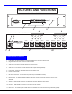
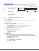
F E A T U R E S A N D F U N C T IO N S F r o n t V ie w N T I R E S C O U T M E N U IN o f V E E M U X -A 6 7 8 9 N e t w o r k T e c h n o lo g ie s In c 1 1 R e a r V ie w 6 2 V ID E O V ID E O 7 8 V ID E O V ID E O T M A D D C E N T E R 5 4 A U D IO N E T W O R K T E C H N O L O G IE S IN C O R P O R A T E D T e l:3 3 0 -5 6 2 -7 0 7 0 1 2 7 5 D a n n e r D r A u ro ra , O H 4 4 2 0 2 F a x :3 3 0 -5 6 2 -1 9 9 9 w w w .n ti1 .
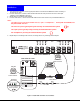
Installation Installation 1. Turn OFF power to all video sources (inputs) that will be connected to the VEEMUX-A before connecting or disconnecting any cables. 2. 3. 4. For each video source, connect a VEXT-xx-MM cable from the video port of the source to a video input (VIDEO-1) of the VEEMUX-A (see Fig. 1). Repeat step 2 for remaining video sources. For each audio source, connect a SA-xx-MM cable from the audio source to the port labeled AUDIO IN 1.
6. 7. 8. 9. 10. 11. 12. 13. Connect a monitor to the port labeled MONITOR 1 on the rear of the VEEMUX-A (see Fig. 2). Repeat step 6 for remaining monitors (outputs). Connect audio output device (speakers) to port labeled AUDIO OUT 1. Repeat step 8 for remaining audio output devices, connecting them to any remaining AUDIO OUT ports. If using RS232 control, connect the video source's serial port to the VEEMUX-A “RS232” with a DINT-xx. Plug the VEEMUX-A to an AC power outlet. Turn ON power to the VEEMUX-A.
Front Panel Keypad Control The front panel keypad and LCD (drawing below) allow the user to view and change current audio and video connections, adjust audio volume and configure the RS-232 control interface. The keypad buttons perform the following functions. ESC Escape back to the main display. 0–9 Used to enter numbers.
• Connecting video only To make a video connection without changing the current audio connection, use any of the following commands: 1. , <▲>, Single digit output port number, or , Single digit input port number, . Ex: <▲> 3 5 2. , <▲>, Double digit output port number, Double digit input port number. Ex: <▲> 03 05 All video outputs can be connected to one video input by using <*>: 1.
RS232Control Control RS232 Remote Connection The RS232 Interface is designed to control the switch via serial (RS232) daisy chain connection from any host computer or other controller with an RS232 communications port. There is, however, a restriction that must be followed: A program must be used that will send an entire command line all at once, not character by character. (The HyperTerminal program in WINDOWS cannot be used, as it sends each character one at a time.
Command Protocol Host controller commands supported by the unit are defined below. All commands should be terminated with a (carriage return). When a command is sent, the entire string is echoed back to the host along with a response from the addressed unit as shown in the command definitions. All characters should be upper case, and all numbers below 10 should have a leading 0 (ex: 1 = 01). NOTE: For units with one output or user port, use 01 for the output select.
CB - Change Baud Rate For All Switches Format: CB 00,BR Successful Response: None Syntax or Transmission Error: ? Behavior: All switches on the serial bus will change their baud rate to the new baud rate. 12 specifies 1200 baud, 24 specifies 2400 baud, 48 specifies 4800 baud, 96 specifies 9600 baud. RS - Internal Reset This feature is not available in the VEEMUX-A.
RO - VIDEO Read Connection For Output/User Port Format: RO SW,OP Successful Response: * IP Syntax or Transmission Error: ? Behavior: This will find out which VIDEO input/CPU port is connected to the specified VIDEO output/user port. AS - AUDIO Connect One Output/User Port To Input/CPU Port Format: AS SW,IP,OP Successful Response: * Syntax or Transmission Error: ? Behavior: This will connect a single AUDIO output/user port to a single AUDIO input/CPU port.
AV - Set Volume Level For Output/User Port Format: AV SW,OP,VV Successful Response: * Syntax or Transmission Error: ? Behavior: On switches that support AUDIO and support volume control of the output/user port, this command will set the volume of the specified AUDIO output/user port from a scale of 00 to 99, which represents a logarithmic volume.
6) Connect All Audio Outputs/Users to an Input/CPU - connect all outputs to an input (Audio ports only) 7) Change Mute Status for Audio Output/User - mute or un-mute the Audio port output 8) Change Volume for Audio Output/User - change Audio port output volume 9) Read Connection for KVM Output/User - read what input is connected to the specified output (KVM ports only) a) Read Connection for Audio Output/User - read what input is connected to the specified output (Audio ports only) b) Read Mute S
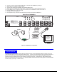
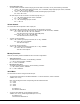
InfraredControl Control(Optional) (Optional) Infrared IRT-20X16 IRT-20X16 Included with IRT-20x16: 1. Move ON / OFF switch to the ON position. • (1) Infrared Transmitter • (2) AA Cell Batteries 1 2 3 4 5 6 7 8 9 10 11 12 13 14 15 16 17 18 19 20 Instructions 1 2 3 4 5 6 7 8 9 10 11 12 13 14 15 16 ON 1. Move ON/OFF switch to the ON position. OFF Select Output First 2. Connect the desired output by selecting one of the 16 touch activated buttons.
DDCSupport Support(Optional) (Optional) DDC DDC information allows the CPU to automatically select the optimal resolution for the monitor by receiving, at power up, information from the monitor concerning its resolution specifications. When DDC Support is installed, the DDC information is acquired from the monitor by the VEEMUX-A switch when the VEEMUX is powered-up. A monitor with DDC support must be connected to MONITOR 1 for this to occur. The DDC information will be made available at every CPU port.
Rack Mounting Instructions Rack mounting Instructions This NTI switch was designed to be directly mounted to a rack. It includes a mounting flange to make attachment easy. Install 4 captive nuts to the rack in locations that line up with the holes (or slots) in the mounting flange on the NTI switch. Then secure the NTI switch to the rack using four 3/16" diameter screws (not provided).