NTI R 1275 Danner Dr Tel:330-562-7070 NETWORK TECHNOLOGIES Aurora, OH 44202 Fax:330-562-1999 INCORPORATED www.networktechinc.
TRADEMARK VEEMUX is a registered trademark of Network Technologies Inc in the U.S. and other countries. COPYRIGHT Copyright © 1999-2007 by Network Technologies Inc. All rights reserved. No part of this publication may be reproduced, stored in a retrieval system, or transmitted, in any form or by any means, electronic, mechanical, photocopying, recording, or otherwise, without the prior written consent of Network Technologies Inc, 1275 Danner Drive, Aurora, Ohio 44202.
TABLE OF CONTENTS Introduction.................................................................................................................................................................... 1 Basic Operation ........................................................................................................................................................... 1 Supported Web Browsers.......................................................................................................................
Specifications............................................................................................................................................................. 27 IRT Troubleshooting .................................................................................................................................................. 27 DDC Support ...........................................................................................................................................................
NTI VEEMUX VIDEO MATRIX SWITCH INTRODUCTION The SM-nXm-15V-LCD (n = number of inputs (video sources), m = number of outputs (monitors)) video matrix switch (VEEMUX) allows any of up to 32 video sources to output to any or all of up to sixteen (16) monitors. The configuration of the VEEMUX is determined at time of order (i.e. 16x4, 8x16, etc.). The bandwidth of the SM-nXm-15V-LCD is 200MHz and video resolutions through 1900 x1200 are supported with no degradation.
NTI VEEMUX VIDEO MATRIX SWITCH Materials Materials Supplied with this kit: • NTI SM-nXm-15V-LCD Video Matrix switch • IEC Line cord, country specific • 4-#10-32 x 3/4" pan head screws and 10-32 cagenuts (server cabinet mounting hardware) • CD with: a pdf file of this owner's manual the NTI Discovery Tool the Matrix Switcher's Control Program Cables All cables are sold separately. The following tables list the available stocked cables with their length in feet.
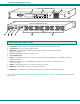
NTI VEEMUX VIDEO MATRIX SWITCH Front View of SM-8X8-15V-LCD 1 2 IN OUT NTI 10 3 Esc Out 6 7 8 9 0 * 1 2 3 4 5 6 Menu In 1 2 3 4 5 Enter 7 8 R DDC Network Technologies Inc 1 2 3 4 5 6 7 8 VEEMUX R Rear View of SM-8X8-15V-LCD ETHERNET 4 5 6 R S 2 3 2 NTI R 1275 Danner Dr Aurora, OH 44202 www.nti1.com Tel:330-562-7070 Fax:330-562-1999 7 7 8 VIDEO 5 6 3 4 VIDEO 1 2 7 8 MONITOR 5 8 6 3 4 MONITOR 1 2 9 FEATURES AND FUNCTIONS 1.
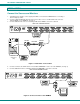
NTI VEEMUX VIDEO MATRIX SWITCH INSTALLATION Connect the Sources and Monitors 1. 2. 3. Turn OFF power to all video sources (inputs) that will be connected to the VEEMUX before connecting or disconnecting any cables. Connect a VEXT-xx-MM cable from the video port of a video source to a 15HD female video connector labeled VIDEO 1 on the VEEMUX. (See Fig. 1) Connect additional video sources to remaining 15HD female VIDEO x connectors as desired.
NTI VEEMUX VIDEO MATRIX SWITCH Connect RS232 RS232 control can be achieved using a separate user terminal or CPU with a terminal program. To make a terminal connection, connect a serial cable (specifications on page 31) between the user terminal and the 9 pin DIN female connector on the VEEMUX labeled "RS232". (See Fig. 3) Rear View of SM-8X8-15V-LCD R S 2 3 2 NTI R 1275 Danner Dr Aurora, OH 44202 www.nti1.
NTI VEEMUX VIDEO MATRIX SWITCH Power Up 1. 2. 3. Plug the VEEMUX into an AC power outlet. Turn ON power to the VEEMUX. Turn ON power to the video sources and monitors connected to the VEEMUX. LED MATRIX (not available on all models) The LED Matrix is a grid of LEDs on the front panel of the VEEMUX. This grid is used to provide a visual indication of all connections between video sources and destinations.
NTI VEEMUX VIDEO MATRIX SWITCH CONTROL OPTIONS The VEEMUX video matrix switch has four methods of control: • Front Panel LCD with Keypad • Directly via an RS232 Interface • Remotely via Ethernet (rack mount models only) • Infrared Remote (optional). Every unit comes standard with the Front Panel LCD with Keypad, and RS232 built in. Rack mount models also include Ethernet connection. If desired, the Infrared option must be requested at the time of the order.
NTI VEEMUX VIDEO MATRIX SWITCH Scan Mode Scan Mode causes an output port to automatically switch from one input port to the next consecutive input port after a specified period of time (referred to as the dwell time). Port switching will continue indefinitely and no ports will be skipped, whether there are video sources connected to them or not. If desired, the VEEMUX can be configured to skip the scanning of specific ports using the RS232 Command Protocol (page 9) or Telnet (page 13).
NTI VEEMUX VIDEO MATRIX SWITCH On the DB-9 female connector, pins 4 (DSR) and 6 (DTR) are shorted and pins 7 (CTS) and 8 (RTS) are shorted. Therefore, host handshaking is bypassed and TXD and RXD are the only active signals. A straight through DB-9 cable (not null modem) will work for most CPUs. To daisy chain multiple units, use NTI Matrix-Y-1 "Y" cables, except for the last unit connected. (see Fig 6). For a pinout of the Matrix-Y-1 cable, see page 32.
NTI VEEMUX VIDEO MATRIX SWITCH Command Definitions (Cont'd) Command String Good Response Description RS SW RV SW,00 RU SW EA SW,ip * *string\0 *IP,OP * EM SW,ip * EG SW,ip * ET SW,timeout * RA SW * ip RM SW * ip RG SW * ip RT SW * timeout Internal Reset Read NTI Version String Read Unit Size Set the IP address, ip is in xxx.xxx.xxx.
NTI VEEMUX VIDEO MATRIX SWITCH Matrix Switcher's Control Program For Windows 9X, NT, 2000 AND XP The Matrix Switcher's Control Program is an easy and powerful graphical program that controls NTI matrix switches through an RS232 interface. The Matrix Switcher's Control Program is included on the CD packaged with the VEEMUX.
NTI VEEMUX VIDEO MATRIX SWITCH Ethernet Operations Key 1) Selection Set Unit IP Address 2) Set Unit Subnet Mask 3) Set Unit Default Gateway 4) Set Unit Website Timeout 5) 6) 7) 8) Read Unit IP Address Read Unit Subnet Mask Read Unit Default Gateway Read Unit Website Timeout Description - enter the desired IP address in xxx.xxx.xxx.xxx format - number of digits is minimum 1 and maximum 3 for each field. Leading zeroes are accepted - enter the desired IP address in xxx.xxx.xxx.
NTI VEEMUX VIDEO MATRIX SWITCH ETHERNET CONTROL Telnet Interface The Telnet Interface enables the user to control the switch using telnet client through an Ethernet connection. The telnet server listens on port 2000. To access the telnet interface, using the current IP address type the following in a command shell: telnet 192.168.1.30 2000 The VEEMUX will prompt the user for a password. The user must enter the password followed by . The factory default password is "admin".
NTI VEEMUX VIDEO MATRIX SWITCH Notes: 1. The commands must be typed exactly as shown in the chart. The commands are case sensitive. 2. If a mistake is made, the user must backspace to the beginning and completely retype the command. 3. If a command is sent that the VEEMUX does not recognize or exceeds the configuration of the switch, the reply "?" may be received. Check the command syntax and try again. 4. To quit the telnet session, press the keyboard keys .
NTI VEEMUX VIDEO MATRIX SWITCH Video Switch Page The Video Switch page (right) displays the active connections (shown in orange) and enables the user to control the video connections of the VEEMUX. Up to 100 different connection configurations can be saved and later recalled by any connection method. Note: If changes are made using the keypad (pg.7) or by another user through the web interface, you must refresh the screen using your browser to see those changes.
NTI VEEMUX VIDEO MATRIX SWITCH To save a configuraton, from the Stored Configurations user interface, use the drop-down list to select the desired slot (numbers 0-99) to save the active configuration into and press the Save button. Note: This will save the currently active configuration on the VEEMUX. If changes have been made in the web interface without first pressing the Submit button, those changes will not yet be part of the active configuration.
NTI VEEMUX VIDEO MATRIX SWITCH Figure 11- Web interface Serial Setup page Changes to the Serial Address and Serial Speed (Fig. 11) do not require a reset and will take effect immediately. Video Input Names Note: Only the changes to the port directly to the left of the Save button will be saved. All other changes to ports without pressing the port's respective Save button will be discarded. All port names must be no more than 12 characters in length and only alphanumeric characters may be used.
NTI VEEMUX VIDEO MATRIX SWITCH Output Names From the Administration menu, the Output Names page can be displayed. This page enables the Administrator to change the names of the output ports displayed on the Switch page. To change an Output Name, enter the name of the port for the desired output port number, and press "Save". Figure 13- Output Port Names Scan Mode From the Administration menu the "Output Scan Mode Settings" page can be displayed.
NTI VEEMUX VIDEO MATRIX SWITCH Update Firmware For updating the Ethernet Control, use this section and insert the file v1_x.bin For updating the Front Panel LCD, use this section and insert the file rmtlcd_va_1_x.
NTI VEEMUX VIDEO MATRIX SWITCH Change Password Page Figure 16- Web interface Password page Use this page to change the password for accessing the web interface. (This password is also used for the telnet interface.) Be sure to make note of the new password exactly as it is case sensitive. The password must be between 5 and 16 characters in length and can be alphabetical or numeric. Help Page This page explains the purpose of each of the other pages in the VEEMUX web interface.
NTI VEEMUX VIDEO MATRIX SWITCH Logout Page Figure 18- Web interface Logout page This page will enable the user to end the session and close the web interface connection. Click on the "Press Here to Continue Logout" button to exit the VEEMUX web interface. Note: The connection will timeout automatically after a preset period of inactivity, configurable on the Web Setup page.
NTI VEEMUX VIDEO MATRIX SWITCH DEVICE DISCOVERY TOOL In order to easily locate the VEEMUX on a network, or to change network settings, the NTI Device Discovery Tool may be used. A link to the Discovery Tool is provided on the web page that appears when you insert the instruction manual CD provided into your CD ROM drive. Click on the link or browse the CD and click on the file discover.html . This will open your browser and display the Device Discovery Tool page.
NTI VEEMUX VIDEO MATRIX SWITCH INFRARED CONTROL (Optional) The IRT-64X32 (or IRT) is an infrared remote transmitter that enables the user to control up to four (4) NTI VEEMUX Video Matrix switches via an infrared receiver from up to 50 feet away (with an unobstructed view). The IRT is battery-powered and always ready to use. The IRT will have a blank display unless an action is being selected by the user.
NTI VEEMUX VIDEO MATRIX SWITCH How To Use The IRT The IRT-64X32 enables the user to control the connections of up to 32 input ports and 16 output ports on up to four (4) separate NTI video matrix switches. When any key is pressed, the IRT will power ON. A number key should always be pressed first unless a change to the configuration is desired (see "Set Configuration" on page 24). When a number key is pressed the LCD will display that number blinking.
NTI VEEMUX VIDEO MATRIX SWITCH Change Output Port Press the desired port number. If there is no change in the desired output port, the output port must still be selected. As the digits are selected, the last number entered will blink. The LCD will also display the current switch number followed by the decimal point. With the desired port number selected, point the IRT at the switch/receiver and press the "OUT" button to transmit the selection and make the change.
NTI VEEMUX VIDEO MATRIX SWITCH Set Configuration The IRT-64x32 factory default setting is 32 inputs and 16 outputs. When the batteries are changed the setting will return to the default value. At the default setting the IRT has the ability control any matrix switch with up to 32 inputs and 16 outputs without changing the configuration. However, when controlling smaller switches without changing the configuration it is up to the user to press valid number(s).
NTI VEEMUX VIDEO MATRIX SWITCH Battery Replacement The IRT has a low-battery indicator to let the user know when it is time to change the batteries. The right-hand decimal point in the LCD display will illuminate (see illustration below). This will stay illuminated while the IRT is in use until the batteries are changed or the battery charge is too low for the IRT to operate. To Change The Batteries: 1. Remove slide cover on rear of unit. 2. Remove old batteries carefully. 3.
NTI VEEMUX VIDEO MATRIX SWITCH DDC SUPPORT (Optional) DDC information allows the CPU to automatically select the optimal resolution for the monitor by receiving, at power up, information from the monitor concerning its resolution specifications. When DDC Support is installed, the DDC information is acquired from the monitor by the VEEMUX-A switch when the VEEMUX-A is powered-up. A monitor with DDC support must be connected to MONITOR 1 for this to occur.
NTI VEEMUX VIDEO MATRIX SWITCH RS232 UPGRADE OF THE FRONT PANEL LCD FIRMWARE The firmware in the front panel LCD can be upgraded to include the latest features available using either the RS232 port (below) or Ethernet Control (page 19). Follow the procedure below to use the RS232 method to update the Front Panel LCD firmware in the VEEMUX. To prepare, first download the rmtlcd_va_1_x. hex file (x= the current firmware version) from the NTI Video Matrix Switch website http://www.networktechinc.com/vmtx.
NTI VEEMUX VIDEO MATRIX SWITCH 5. Press to load the firmware (hex) file. This will prepare the file for transfer to the VEEMUX. If the file fails to load, press the key to clear the old firmware, and press to load it again. 6. When the message “Start sending file via Xmodem protocol..”' appears, the VEEMUX is waiting for the Firmware file to be uploaded. A box or some other characters may be displayed repeatedly on the line below this message while the VEEMUX waits; this is normal. 7.
NTI VEEMUX VIDEO MATRIX SWITCH RS232 CONNECTION CABLES Pinout of RS232 port on VEEMUX The VEEMUX RS232 serial port is a DB-9F (female) connector configured as a DCE (data communication equipment) port. The RS232 port interface signals are listed below, including equivalent CCITT V.24 identification, and signal direction: DB-9F pin # 1 2 3 4 5 6 7 8 9 Common name N/a TxD RxD DSR SG DTR CTS RTS N/a EIA name N/a BA BB CC AB CD CB CA N/a CCITT name N/a 103 104 107 102 108.
NTI VEEMUX VIDEO MATRIX SWITCH Pinout for Matrix Y-1 Cable Wiring Schematic of Matrix-Y-1 cable 9D Male (Unit #1) 9D Female (Source) 2 9D Male (Unit #2) 3 3 3 5 5 5 2 2 7 8 1 4 6 Not connected to source connector Jumper Jumpers Arrows indicate signal direction. RACK MOUNTING INSTRUCTIONS This NTI switch was designed to be directly mounted to a rack. It includes a mounting flange to make attachment easy.
NTI VEEMUX VIDEO MATRIX SWITCH SPECIFICATIONS General Information DESCRIPTION Operating temperature Storage temperature Power requirements Fuse protection Video Connectors Maximum Resolution Video Signal : Video Bandwidth Sync Ethernet Connector RS232 Connector SPECIFICATION -18°C - 55°C (0°F - 131°F) (17-90% non-condensing RH) -30°C - 60°C (-20°F-140°F) (17-90% non-condensing RH) 110 or 220VAC @ 50 or 60Hz 2A 240VAC Fast-blo 15HD female 1920 x 1200 @ 85Hz RGB analog (75 ohms, 0.
NTI VEEMUX VIDEO MATRIX SWITCH TROUBLESHOOTING Problem No Video Solution Check power – power ON, power cable connected Check video cabling – make sure cables are secured Check connections – make sure you’re connected to an active input SAFETY STATEMENTS Grounding These products have protective earth ground terminals and are built with full attention to consumer safety.