
INSTALLATION / USER GUIDE 4/2-Port USB KVM Switch UNIMUX-USBV-4, UNIMUX-USBV-2


2
FEATURES AND FUNCTIONS
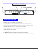
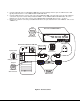
1. Power Switch- to power up or power down the UNIMUX-USBV-4 USB KVM switch.
2. Mode Status LEDs- for visual indication of switch operating mode
3. CPU Status LEDs- for visual indication of switch connection between the user and a specific CPU
4. CPU Select Switch- press to manually switch to a specific CPU or to change the switch operating mode
5. MONITOR- 15HD female connector- for connection of the user video monitor
6. VIDEO x- 15HD female connectors- for connecting video cables from CPUs
7. 5VDC- connection jack for the AC adapter
8. CPU x- USB type B female connectors-for connection of USB device cables from CPUs
9. USB DEVICES- USB type A female connectors- for connection of user USB device(s)
10. DDC button- for manual update of DDC information between the monitor and the CPU(s) attached (optional)
FEATURES AND FUNCTIONS
F E A T U R E S A N D F U N C T I O N S
C P U 4 C P U 3 C P U 2 C P U 1
6
9
7
5
5 V D C
2 A
-
+
N E T W O R K T E C H N O L O G I E S I N C O R P O R A T E D 1 2 7 5 D a n n e r D r i v e , A u r o r a O h i o 4 4 2 0 2 3 3 0 - 5 6 2 - 7 0 7 0 w w w . n t i 1 . c o m
N T I
R
8
U S B
D E V I C E S
U N I M U X
1
2 3
4
S C A N
C O M
M A N D
3
2
1
4
F r o n t V i e w o f U N I M U X - U S B V - 4
B R O A D
C A S T
M O N I T O R
V I D E O 1V I D E O 2V I D E O 3V I D E O 4
R e a r V i e w o f U N I M U X - U S B V - 4
N T I
R
N e t w o r k T e c h n o l o g i e s I n c
1 0
D D C