
Network Card User Manual

22
Appendix B- General Information
DESCRIPTION SPECIFICATION
Dimensions 19"W x 10" D x 1.75" H
Operating temperature 0°C - 55°C (32°F - 131°F)
Power requirements 120 or 240VAC @ 50 or 60Hz
Video bandwidth 200 MHz (without cables)
Video sync TTL
Chassis material Aluminum
Appendix C- Cables
NTI # DESCRIPTION
VMTINT-3/6/10/15/25 Interface PS/2 Keyboard and Mouse and VGA video to Nodemux-HD switch
SMTINT-3/6/10/15/25 Interface SUN Keyboard and Mouse and VGA video to Nodemux-HD switch
VMTINT-3/6/10/15/25-MM Interface PS/2 CPU to Nodemux-HD switch
SMTINT-3/6/10/15/25-MM Interface SUN CPU to Nodemux-HD switch
Legend:
MM- male connectors on both ends
If the cable desired is not listed above, please visit our website at
http://www.nti1.com for a complete listing of the cables and
adapters we offer, or call us at (800) 742-8324 (800-RGB-TECH) or (330) 562-7070.
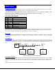
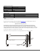
Appendix D- Rack mounting Instructions
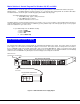
If this NTI switch was designed to be directly mounted to a rack, it includes a mounting flange to make attachment easy.
Install 4 captive nuts to the rack in locations that line up with the holes (or slots) in the mounting flange on the NTI switch.
Then secure the NTI switch to the rack using four 3/16" diameter screws (not provided). Each screw should be of sufficient
length to go completely through the NTI mounting flange, rack frame and fully engage all threads in the captive nut. We suggest
installing additional rails to the rack frame to support the weight of the switch. Be sure to tighten all mounting screws securely.
Do not block power supply vents in the NTI switch chassis (if provided) .
Attach all cables securely to the switch and where necessary supply adequate means of strain relief for cables.
1275 Danner Drive
Aurora Ohio 44212
NTI
NETWORK
TECHNOLOGIES
INCORPORATED
Tel: 330-562-7070
Fax: 330-562-1999
R
www.nti1.com
Rack
3/16” Diameter
Screws
Captive
Nuts
Support
Rail