NTI R 1275 Danner Dr Tel:330-562-7070 NETWORK TECHNOLOGIES Aurora, OH 44202 Fax:330-562-1999 www.networktechinc.
TRADEMARK KEEMUX is a registered trademark of Network Technologies Inc in the U.S. and other countries. COPYRIGHT Copyright © 1999-2007 by Network Technologies Inc. All rights reserved. No part of this publication may be reproduced, stored in a retrieval system, or transmitted, in any form or by any means, electronic, mechanical, photocopying, recording, or otherwise, without the prior written consent of Network Technologies Inc, 1275 Danner Drive, Aurora, Ohio 44202.
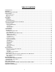
TABLE OF CONTENTS INTRODUCTION............................................................................................................................................................. 1 MATERIALS .................................................................................................................................................................... 1 FEATURES AND FUNCTIONS...........................................................................................................................
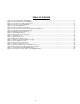
TABLE OF FIGURES Figure 1- Keyboard dip-switch configuration...................................................................................................................................... 3 Figure 2- Connect the monitor to the KEEMUX ................................................................................................................................. 3 Figure 3- Connect the user keyboard and mouse..............................................................................................
NTI KEEMUX Series PS/2 KVM Switch INTRODUCTION The KEEMUX PS/2 KVM switch (KEEMUX) enables access to several IBM PC-AT, PC-AT Clone or PS/2 CPUs from one monitor, keyboard and PS/2 mouse (up to 32 CPUs as a single switch or 152 CPUs when switches are cascaded). These CPUs can be file servers, network managers, etc. Internal microprocessor driven circuitry allows all CPUs to be booted simultaneously and error free with only one keyboard and mouse present.
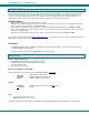
NTI KEEMUX Series PS/2 KVM Switch FEATURES AND FUNCTIONS Front View of KEEMUX-P8 3 NTI 2 1 R Network Technologies Inc Scan 2 1 3 4 5 6 7 Broad Com cast mand 1 8 8 On 5 4 1. Power ON/OFF switch 2. Mode LEDs- for visual indication of switch mode status 3. CPU Status LEDs- for visual indication of connection between the user and a specific CPU. 4. CPU Select Switches- push to manually switch to a specific CPU 5. Dip-switches- for configuring keyboard type and cascaded switches 6.
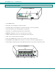
NTI KEEMUX Series PS/2 KVM Switch INSTALLATION Prepare To Connect 1. Before connecting the KEEMUX to the CPUs, make sure all CPUs, the monitor, and the KEEMUX are turned OFF. ! 2. WARNING! DAMAGE MAY OCCUR TO THE CPU IF POWER IS NOT DISCONNECTED BEFORE CONNECTING OR DISCONNECTING CABLES. The dip-switches on the front panel are configurable for several tasks. Switches 1-6 are used for cascading actions (see CASCADING on page 5) and switches 7 and 8 are for keyboard configuration.
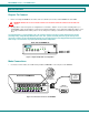
NTI KEEMUX Series PS/2 KVM Switch 2. Connect the keyboard cable to the 6 pin miniDIN female port labeled “KEYBOARD” on the rear panel of the switch. Connect the mouse cable to the 6 pin miniDIN female port labeled “MOUSE” on the rear panel of the KEEMUX.
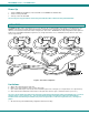
NTI KEEMUX Series PS/2 KVM Switch Power Up 1. 2. 3. Turn the KEEMUX power ON first. The mode LEDs on the KEEMUX should flash twice. Turn the monitor power ON. Turn any or all of the CPUs ON. FYI: Do not press any port buttons on the front panel until the PORT 1 LED on the front panel illuminates. CASCADING The KEEMUX switch can be expanded to access up to 152 CPUs by cascading multiple units together, as illustrated below.
NTI KEEMUX Series PS/2 KVM Switch Configuration All 4, 8, and 16-port units are configured using the 8-position dip-switch (located on the front of each unit) according to tables 1 and 2 below.
NTI KEEMUX Series PS/2 KVM Switch 2. Connect Local CPUs to any remaining consecutive ports on the master as described under INSTALLATION on page 3. 3. Connect the RMT extension cables: a. With an RMT extension cable (REXT-SR-xx), connect the master’s “DAISY OUT” port to slave #1’s “DAISY IN” port. b. With another RMT extension cable, connect slave #1’s “DAISY OUT” port to slave #2’s “DAISY IN” port. (See Fig. 7 below.) c. Apply additional RMT extension cables until all slave units are connected together.
NTI KEEMUX Series PS/2 KVM Switch Keyboard Control Keyboard control of the KEEMUX can be achieved using either of two methods: • Basic Command Mode- operated strictly by using keyboard commands as instructed below. Basic Command Mode is only applicable if the OSD option is not built into the switch. • OSD Command Mode (optional)- operated using the keyboard and mouse in conjunction with On Screen Display (OSD) menus superimposed onto the monitor. If OSD is built in, use the menus as instructed on page 12.
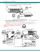
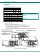
NTI KEEMUX Series PS/2 KVM Switch Port assignments ( KEEMUX-P4 ) PORT 3 PORT 4 - PORT 1 PORT 2 V I D E O V I D E O V I D E O V I D E O 4 3 2 1 C P U 4 5VDC 2A + CPU 4 C P U 3 CPU 3 C P U 1 C P U 2 CPU 2 CPU 1 NTI M O N I T O R R 1275 Danner Dr Aurora, OH 44202 www.nti1.com Tel:330-562-7070 Fax:330-562-1999 Mouse Keyboard Daisy Out Daisy In PS/2 DEVICES Figure 8- Connections grouped by port number Please note: If the switches are being cascaded (such as that illustrated in Fig.
NTI KEEMUX Series PS/2 KVM Switch OSD CONTROL (Optional) OSD superimposes a menu system on the user’s video screen with a list of all connected CPUs. OSD allows CPUs to be named (with up to 12-character names). OSD then allows selection of CPUs by that name. Connected CPUs can be listed by name or by port number. OSD Search Mode enables the user to type in the first few characters of the CPU's name and the OSD will locate it. Help screens assist with all OSD functions.
NTI KEEMUX Series PS/2 KVM Switch User Login Mode (Cont'd) Function: Submit user name/password Exit User Login Mode and return to previous mode. This function is only available if security is not currently active. Keystroke: Enter If the password submitted is incorrect, the user will not be able to proceed. If the password submitted is correct, the user will proceed to the maintenance menu for additional feature options. Esc .
NTI KEEMUX Series PS/2 KVM Switch Function: Add character to password string or verify password string Delete previous character in edited string Save new password.
NTI KEEMUX Series PS/2 KVM Switch User Access Functions Introduction The OSD menu enables a user to name the CPUs connected to the KEEMUX and connect to them using that name from a single keyboard and mouse. The OSD is positioned on the user's monitor, displaying 8 CPU names at a time. The screen can be used for switching as well as editing the CPUs’ names. Through the OSD menu, the user can control the KEEMUX to cycle through all modes of operation: COMMAND, SCAN, BROADCAST and NORMAL.
NTI KEEMUX Series PS/2 KVM Switch OSD Command Mode (Cont'd) Function: Selects the last port on the switch Switch to a selected port Exit OSD Command Mode Keystroke: End Enter Esc The mouse can also be used to control Command Mode. The mouse cursor can be moved to the Scan, Help, and Exit fields where the user can then click on the left mouse button to perform that function. Ports listed on the screen can be selected by moving the cursor onto that port and clicking.
NTI KEEMUX Series PS/2 KVM Switch Edit Mode Edit Mode allows the user to modify the names of the CPUs connected to the switch. Names of CPUs can be up to 12 characters in length. To enter Edit Mode press + from Command Mode. When in Edit Mode, multiple keystroke combinations are not valid (+, +, + , and
will all type a “P” to the display - lower case letters cannot be typed). After changes have been made the user will be prompted by the menu to save the changes.
NTI KEEMUX Series PS/2 KVM Switch Search Mode Search Mode allows the user to enter and maneuver through a list of CPU names. As the user types, the best matching CPU name is selected. The list of CPUs may also be searched for a specific (or similar) name. From Command Mode, type any alphabetical or numeric character to enter Search Mode. The following commands are valid when the search option has been invoked from Command Mode.
NTI KEEMUX Series PS/2 KVM Switch Maintenance Mode (Cont’d) Function: Keystroke: Make OSD window taller T Make OSD window shorter S Change user password. (Present only when a standard user is logged in.) P Log current user out and return to User Login Mode. Q Activate security features. Present only when security is available but not active. A Enter Administration Mode. Option present only when administrator is logged in.
NTI KEEMUX Series PS/2 KVM Switch RS232 CONTROL (Optional) Rear View of KEEMUX-P4-RS - 5VDC 2A + NTI C P U 4 R 1275 Danner Dr Aurora, OH 44202 www.nti1.
NTI KEEMUX Series PS/2 KVM Switch Unit Address and Loop Back To allow multiple units to be controlled from a single CPU port, the RS232 control interface is designed to allow "daisy chaining" up to 15 units. By setting the appropriate RS232 dip switches, each unit can be given a unique address (1-15). Then the unit will only respond to commands on the bus if its address is embedded in the command. Use the table below to set the unit address.
NTI KEEMUX Series PS/2 KVM Switch Command Protocol CPU controller commands supported by the unit are defined below. All commands should be terminated with a (carriage return). When a command is sent, the entire string is echoed back along with a response from the addressed unit . All characters in the command string should be upper case, and all numbers below 10 should have a leading 0 (ex: 1 = 01). As command strings are sent, the inner character delay cannot exceed 500 milliseconds.
NTI KEEMUX Series PS/2 KVM Switch NTI Switch Control Program For Windows 9X, NT, 2000 And XP The Matrix Switcher's Control Program is an easy and powerful graphical program that controls NTI switches through an RS232 interface. The NTI Switch Control Program is included on the CD packaged with the KEEMUX. The NTI Switch Control Program is downloaded by clicking on the link "Download NTI Switch Control Program" found on the webpage that opens when you insert the instruction manual CD into your CD ROM drive.
NTI KEEMUX Series PS/2 KVM Switch 8) Change Volume for Audio Output/User (only applicable to models with audio support) - change Audio port output volume 9) Read Connection for Output/User - read what input is connected to the specified output a) Read Connection for Audio Output/User (only applicable to models with audio support) - read what input is connected to the specified output b) Read Mute Status and Volume for Audio Output/User (only applicable to models with audio support) - read the volume
NTI KEEMUX Series PS/2 KVM Switch HOW TO DISABLE OPERATING MODES The operating modes of the KEEMUX can be disabled if a user desires to do so. The Command Mode can be disabled which would also disable the Scan and Broadcast Modes, or, the Scan and/or Broadcast Modes can be individually disabled leaving the other features in Command Mode enabled. To disable these operating modes, the user must get access to the jumper block.
NTI KEEMUX Series PS/2 KVM Switch NOTE: Before proceeding, it is important to discharge any static charge you may be carrying by touching any large metal object (away from the KEEMUX). 4. With it loosened, grasp firmly the front panel and slide the front panel up out of the slots in the plastic case that support it. Once clear of the case, pivot the assembly forward approximately 1", just enough to provide access to the jumper block. (See Fig. 19.
NTI KEEMUX Series PS/2 KVM Switch AUDIO SUPPORT (Optional) Audio support provides the following additional features: • Audio signals from the same CPU that keyboard, mouse, and video signals are from can be received by the user. • Audio inputs accept any standard line level audio (1Vrms or 2.5Vp-p). • Audio outputs are capable of driving an 8 Ohm speaker load with 200mW of continuous RMS power.
NTI KEEMUX Series PS/2 KVM Switch SPECIFICATIONS FOR STRAIGHT-THROUGH RS232 SERIAL CABLE KEEMUX to PS2 CPU (9 PIN) KEEMUX 9 pin Signal Function Pin # Direction RxD 3 TxD 2 CTS 7 RTS 8 DSR 4 DTR 6 SG 5 PS/2 CPU 9 pin Pin # Function 3 TxD 2 RxD 7 RTS 8 CTS 4 DTR 6 DSR 5 SG 1 6 4 3 2 7 8 5 9 Mating Face of a 9D Male Terminals 7 and 8 are jumpered together and terminals 4 and 6 are jumpered together.