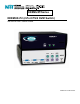
KEEMUX® Series KEEMUX-P2 (2-Port PS/2 KVM Switch) INSTALLATION / USER GUIDE MAN049 Rev Date 4/8/2004
WARRANTY INFORMATION The warranty period on this product (parts and labor) is two (2) years from the date of purchase. Please contact Network Technologies Inc at (800) 742-8324 (800-RGB-TECH) in the US and Canada or (330) 562-7070 (worldwide) or at our website at http://www.networktechinc.com for information regarding repairs and/or returns. A return authorization number is required for all repairs/returns. COPYRIGHT Copyright© 2004 by Network Technologies Inc. All rights reserved.
TABLE OF CONTENTS INTRODUCTION ............................................................................................................................................................................... 1 MATERIALS...................................................................................................................................................................................... 1 FEATURES AND FUNCTIONS.......................................................................................
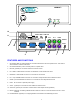
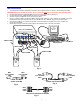
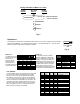
NTI KEEMUX R R Network Technologies Inc Remote CPU SELECT 3 CPU 1 CPU 2 1 2 12 RS232 AUD 2 AUD 1 AUD OUT 11 PC 2 OFF 12345678 ON 6 PC 1 5 4 6 3 2 USER 5 4 6 3 1 2 MOUSE 5 4 3 1 2 1 KYBD 9 6 10 5 4 3 2 PC 2 VIDEO PC 1 VIDEO 4 6 1 5 4 6 3 2 5 4 1 3 2 1 PWR MONITOR 6 5 7 8 FEATURES AND FUNCTIONS 1. 2. CPU Status LEDs- for visual indication of connection between the user and a specific CPU.
INSTALLATION 1. Turn OFF power to all CPUs that will be connected to the NTI Switch before connecting or disconnecting any cables. WARNING! Damage to the CPU may result if power is not turned OFF before connecting or disconnecting cables. 2. 3. 4. 5. 6. 7. Connect PS/2 keyboard to “USER KEYBD” port on the rear panel of the switch. (See Fig. 1) Connect PS/2 mouse to “USER MOUSE” port on the rear of the switch. Connect monitor to “MONITOR” port on the rear of the switch.
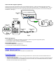
Units with audio support (optional) Connect the 3.5mm plug from speakers to the 3.5mm jack labeled "AUD OUT". Attach SA-xx-MM audio cables (purchased separately) between the audio port on each CPU and the 3.5mm audio jacks marked "AUD 1" on the KEEMUX switch. Be sure to connect the audio cables from each CPU to audio jacks of the same number as the keyboard, mouse, and video cable ports connected to. ( See Fig. 5). 3.
Keyboard Control In order to control the switch with the keyboard, COMMAND Mode must be enabled. To enter/exit COMMAND Mode from the keyboard: (ACCENT ~ Press Ctrl KEY) + ` COMMAND Mode When the COMMAND Mode is ON, all 3 status LEDs on the keyboard will illuminate to indicate that COMMAND Mode is enabled and the following functions are available: (NOTE: The user must exit COMMAND Mode in order to type to a CPU.
Keyboard Features The keyboard configuration of each CPU is saved in the NTI Switch. For example, if the CPU attached to Port 2 had CAPS LOCK and NUM LOCK selected the last time that CPU was accessed, then they will automatically be set when that CPU is accessed again. AUDIO SUPPORT (Optional) Audio support provides the following additional features: • Audio signals from the same CPU that keyboard, mouse, and video signals are from can be received by the user.
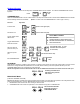
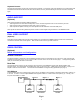
Wiring Schematic of Matrix-Y-1 cable 9D Male (Unit #1) 9D Female (Source) 9D Male (Unit #2) 2 3 3 3 5 5 5 2 2 7 8 1 4 6 Not connected to source connector Jumper Jumpers Fig. 7 Dipswitches The dipswitches located next to the RS232 connection (Fig. 8) are used to configure the baud rate and address of the KEEMUX. The default baud rate is 9600. The default address is 1. Use the charts below to change the baud rate and address as needed. OFF 12345678 ON Fig.
RS232 Interface Test Program RS232 communication is configured using the RMTEST program, located on the supplied floppy disk. This software allows a user to test the functions of an NTI KEEMUX or Multi-user/Multi-platform switch RS232 interface. The RMTEST program generates a main menu with the 3 selections described below: MAIN OPTIONS 1. Matrix Options 2. Setup Options 3. Quit - send commands to the unit.
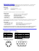
RS232 Port (DB-9 MALE) PIN SIGNAL FUNCTION 1 No connection 2 RXD Receive data 3 TXD Transmit data 4 DTR Data terminal ready 5 GND Signal ground 6 DSR Data set ready 7 RTS Request to send 8 CTS Clear to send 9 No connection 1 2 6 4 3 8 7 5 9 Mating Face of DB-9 Male REMOTE (RMT-2-ST) 5 DIN SIGNAL DESCRIPTION 1 LED1 TTL output, low = port 1 selected 2 LED2 TTL output, low = port 2 selected 3 SWT TTL of contact closure input (10K pullup) 4 GND Ground 5 PWR +5V for LEDs, limited to 20mA Low= < .
SERIAL NO.: DATE: INSPECTED BY: KEEMUX-P2 KEEMUX-P2-RMT KEEMUX-P2-AUD KEEMUX-P2-DV Man049 Rev.