Operation Manual Universal Video Interface Series IN2000 Analog / TTL / ECL Video Interface IN2001 Analog / TTL / ECL Video Interface ®
TABLE OF CONTENTS Description / Features ....................................................................................................................1 IN2000 / IN2001 Differences .........................................................................................................2 Input Compatibility .......................................................................................................................2 Output Compatibility.........................................................
1 DESCRIPTION The IN2000 and IN2001 are universal computer video interfaces designed to work with Analog, TTL, and ECL computer video signals. Like other INLINE interfaces, the IN2000 / IN2001 carry out three primary functions: Signal Splitting - these interfaces allow for the simultaneous connection and viewing of both the computer’s local monitor and a second output device such as a large screen data projector, monitor, or color printer.
2 IN2000 AND IN2001 DIFFERENCES These two interfaces are virtually identical in function, features, and operation with only a few minor differences as detailed in the chart below: Power Supply: IN2000 External Power Adapter IN2001 Internal Power Supply Size: 1.1" H x 4.8" W x 3.27" D 2" H x 6.75" W x 4.
3 While the input connector on the IN2000/2001 looks like a standard 15 pin HD VGA connector (15 pins in three rows), this input uses proprietary pin connections to accommodate the unit’s universal design. VGA and other signals can not be attached directly to the input without the appropriate IN5100 Series loop cable. OUTPUT COMPATIBILITY The IN2000 / IN2001 output an analog video signal in the RGBS format (Red, Green, Blue, and composite sync) on four BNC connectors.
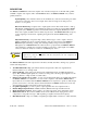
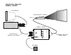
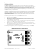
4 INSTALLATION This section offers step-by-step instructions for installing the IN2000 / IN2001. A detailed application drawing showing all equipment connections is included on the next page. 1. Turn the computer and computer monitor off. Disconnect the computer monitor (if present) from the video output port on the computer. 2. The IN5100 Series cables have a pass-through connector (Male and Female) on one end. The passthrough end is connected to the computer and local monitor.
Application Diagram IN2000 / IN2001 Local Monitor Data Projector / Monitor RGBS Input IN2000 / IN2001 Computer CPU VIDEO GAIN HORIZONTAL POSITION RED GREEN/ MONO IN5100 Series Monitor Loop Cable BLUE 2000 ® UNIVERSAL ANALOG / DIGITAL VIDEO INTERFACE Power Supply 12V / 500 mA BLUE CONTROL SYNC IN7000-4 / IN7100-4 RGBS Cable
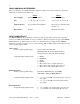
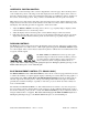
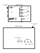
6 HORIZONTAL POSITION CONTROL The location of the horizontal position control is diagrammed on the next page. The horizontal position control adjusts the position of the image on the data display device from left to right (it has no effect on the local computer monitor). This control adjusts through a range of 14 full knob rotations, offering very fine control over the image position. The pot emits a soft click if either extreme position is reached.
IN2000 Top View Horizontal Position Control VIDEO HORIZONTAL GAIN POSITION RED Red Gain GREEN/ MONO Green Gain BLUE Blue Gain 2000 UNIVERSAL ANALOG / ® SYNC BLUE DIGITAL CONTROL VIDEO INTERFACE Blue Enhancement Control Horizontal Position Control IN2001 Top View Blue Enhancement Control VIDEO GAIN BLUE CONTROL G B Blue Gain R Green Gain Red Gain
8 INTERNAL CONTROLS The IN2000 and IN2001 have been designed with several controls which may be used by qualified technicians to adjust specialized signal parameters. These controls, consisting of 10 dip switches and one adjustment pot, are infrequently used and do not require adjustment for normal daily operation. For convenience, the IN2001 has been designed with two access slots in the bottom of the unit so the case does not need to be opened to change the dip switches and adjustment pot.
9 Horizontal Blanking Control (TTL Only) The Horizontal Blanking Control functions only with TTL digital input signals. This control (location shown on Page 8) will not need to be adjusted on a regular basis. The following image symptoms may indicate that the control is misadjusted: missing background colors, horizontal dark bars across the screen, or missing foreground colors.
10 Disable Horizontal Position Control Turning Dip Switch #6 to ON disables the Horizontal Position Control. This setting should only be used with Composite Sync or Sync on Green input signals. If Switch #6 is set to ON when using input signals with separate Horizontal and Vertical syncs, the unit will not output any sync signal, causing the video projector or data monitor attached to the IN2000 / IN2001 output to loose sync and stop displaying an image.
11 IN5100 SERIES MONITOR LOOP CABLES - PARTIAL LISTING Computer / Graphics Card Cable Model Connector IN5101A IN5106T IN5105T 15 Pin HD 9 Pin D 9 Pin D IN5161A IN5107T IN5111T IN5122T 15 Pin D Internal Harness Internal Harness 9 Pin D COMMODORE Amiga 500 / 1000 / 2000 / 3000 / 4000 IN5147A 23 Pin D WORKSTATIONS & TERMINALS Sun Sparc Station Sun Monochrome Silicon Graphics Iris Indigo NeXT Color NeXT Monochrome IBM 3192 NCD 17C DEC VT420 Kit 1 - BNC - Monochrome 4 - BNC - RGBS or RGsB 5 - BNC - RG
12 INTERFACING TO COMPUTERS WITH BNC OUTPUTS The IN5129A, IN5132A, and IN5133A are special input cables designed for use with workstations and terminals which have BNC video outputs.
13 SPECIFICATIONS IN2000 Universal Computer Video Interface Input Connector type RGB Video Signals Input Impedance Maximum Input Voltage Sync Signals Input Impedance Maximum Input Voltage Horizontal Scan Range Vertical Scan Range Output Connector Type Output Signal Formats RGB Signals Bandwidth Rise and Fall Times Gain Sync Signal Horizontal Pulse Width Vertical Pulse Width Controls External Internal Dimensions Size Shipping Weight Power Power Supply Consumption Approvals ©1996-1997 - INLINE, INC.
14 Parts and Accessories Included IN2000 Adjustment Tool 12V 500 mA Power Supply Operations Manual IN2001 Adjustment Tool AC Power Cable (US only) Operations Manual Optional Accessories IN5100 Series Input Cables See Page 11 for a partial listing of available input cables. For a complete listing of IN5100 Series input cables see the current INLINE Product Catalog.
15 The output image is very bright and overdriven looking with poor contrast. Solution 1: The loop through cable is probably being used without a local monitor and the signal is therefore unterminated. Use either a local monitor or a termination plug at the monitor loopthrough connector on the IN5100 Series cable. If this is not the problem try #2. Solution 2: Verify the gain settings on the IN2000 / IN2001 RGB gain pots. If they are set to a very high gain level, reduce the gain as required.
16 WARRANTY ♦ INLINE warrants the equipment it manufactures to be free from defects in materials and workmanship. ♦ If equipment fails because of such defects and INLINE is notified within two (2) years from the date of shipment, INLINE will, at its option, repair or replace the equipment at its plant, provided that the equipment has not been subjected to mechanical, electrical, or other abuse or modifications.