Model:R718NL3 Wireless Light Sensor and 3-Phase Current Meter Wireless Light Sensor and 3-Phase Current Meter R718NL3 User Manual
Table of Content 1. Introduction....................................................................................................................................................................................... 2 2. Appearance........................................................................................................................................................................................ 3 3. Main Features .............................................................................
1. Introduction The R718NL3 series is a Light Sensor and 3-Phase Current Meter device for Netvox ClassA type devices based on the LoRaWAN open protocol and is compatible with the LoRaWAN protocol. R718NL3 series have different measuring range for different variety of CT.
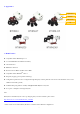
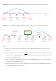
2. Appearance Light Sensor Indicator Function Key CT 3. Main Features Compatible with LoRaWAN protocol 2 sections ER14505 3.
4. Set up Instruction On/Off Power on Insert batteries. (users may need a flat blade screwdriver to open) Turn on Press and hold the function key for 3 seconds till the green indicator flashes once. Turn off Press and hold the function key for 5 seconds till green indicator flashes 20 times. (Restore to factory setting) Power off Remove Batteries. 1.The device will be off after removing the battery and insert it again. Note 2.
Low Voltage Warning Low Voltage 3.2V 5. Data Report The device will immediately send a version packet report along with an uplink packet including current, illuminance and battery voltage. The device sends data in the default configuration before any configuration is done.
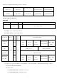
Data report configuration and sending period are as following: Min. Interval Max. Interval Current Change≥ Current Change< Reportable Change (Unit:second) (Unit:second) Reportable Change Reportable Change Any number between Any number between Report Report 30~65535 Min.~65535 per Min. Interval per Max. Interval Can not be 0.
(2) Read device configuration parameters Downlink: 0299000000000000000000 The device returns: 8299003C003C0064006400 (current device configuration parameters) Report Current and Illuminance Data Example Mulitplier1 (1Byte), Battery Current1 Current2 Current3 the real current1 (1Byte, unit:0.
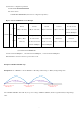
Example#2 based on MinTime = 15 Minutes, MaxTime= 1 Hour, Reportable Change i.e. BatteryVoltageChange= 0.1V. MaxTime Sleeping(MinTime) sleeping sleeping 15th M 0H 30th M sleeping 45th M 1H 2H Wakes up and Wakes up and Wakes up and Wakes up and Wakes up and collects data collects data collects data collects data collects data REPORT 3.6V 3.6V 3.6V 3.6V REPORTS 3.
6. Installation 1. When using it, the back of it can be adsorbed on the iron surface, or the two ends can be fixed to the wall with screws. 2.
2. Open the split current transformer, and then pass the live 1. The single-phase current detector (R718NL3) has a built-in magnet (as the figure below). It can be attached wire through the current transformer according to the to the surface of an object with iron during installation, installation. which is convenient and quick. Note: "L←K" is marked on the bottom of the CT. To make the installation more secure, please use screws (purchased separately) to fix the device to the wall or other 3.
Current Direction The CT terminal should be close to the power terminal as much as possible. R718NL3 CT Phase A Screw Fixation Wire to be detected Screw Fixation Current Direction The CT terminal should be close to the power terminal as much as possible. Current Direction The CT terminal should be close to the power terminal as much as possible.
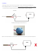
7.1 To determine whether a battery requires activation Connect a new ER14505 battery to a 68ohm resistor in parallel, and check the voltage of the circuit. If the voltage is below 3.3V, it means the battery requires activation. 7.2 How to activate the battery a. Connect a battery to a 68ohm resistor in parallel b. Keep the connection for 6~8 minutes c. The voltage of the circuit should be ≧3.3V 8.