User Manual Version 2.0 NETVOX TECHNOLOGY CO., LTD. Add:No. 21-1 Sec. 1 Chung Hua West Road, Tainan, Taiwan Tel: +886-6-2617641, 2654878 Fax:+886-6-2656120 http://www.netvox.com.
History Version Date Note V1.0 2010-7-16 Initial Release V1.1 2010-10-26 Update the PCB footprint for the module V2.0 2011-07-18 Update the PCB LAYOUT Notes: Hardware version 1.2 Copyright©Netvox Technology Co., Ltd. This document contains proprietary technical information which is the property of NETVOX Technology and is issued in strict confidential and shall not be disclosed to others parties in whole or in parts without written permission of NETVOX Technology.
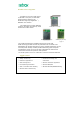
Product Description The ZigBee RF module Z100B offered by NETVOX is low power, 2.4GHz ISM band transceiver based on the TM Ember357 single chip ZigBee Pro / IEEE 802.15.4 solution. The Z100B comes in three different versions. On-board chip antenna, metal antenna and I-PEX version. . Z100B(Metal Antenna) Z100B( I-PEX Antenna) Z100B(Chip Antenna) Figure 1 The Z100B is designed to be SMD-mounted onto a host PCB. SMD-mounting provides the best RF performance at the lowest cost.
9 Versions The Z100B module supports ultra-low-power applications, in combination with long transmission range. The Z100BC version features an on-module chip antenna. It is ideally suited for all multi purpose wireless mesh solutions. The Z100BI version where the RF signal connects to an external antenna ideally suited to optimize antenna directivity and/or extended ranges. Key Features 9 High performance and low power 32-bit ARM Cortex-M3 microprocessor 9 2.4 GHz IEEE 802.15.
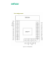
Figure 1 Pin assignment
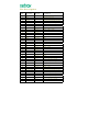
Pin Description Pin NO. 1 Pin name Pin type Description GND Ground GND 2 /RST I Active low chip reset 3 SWDIO I/O Programming and debug interface 4 SWCLK I/O Programming and debug interface 5 VCC Power 2.1V-3.
Debugging interface Pin29~38 of the module are arranged for burning and debugging interface. Mechanical Drawing and Dimensions Figure 2 Mechanical Drawing and Dimensions The module size is 16.0*22.0*3.7mm Antenna and Range Considerations The Z100BC module is delivered with an integrated antenna. This is highly recommended for most applications, as this gives a very compact solution containing all the critical RF parts within the module.
PCB Layout Recommendations Figure 3
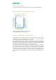
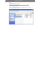
Debugging program installation Steps: Install EMBER InSight Desktop I. Install the EMBER InSight Desktop onto your PC for burning unencrypted EM357 firmware. On the PC, select and double-click on the executable InSight_Desktop_Installer_2.1b94, then follow the prompt to complete the installation.
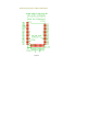
II. Wiring Setup before Burning Firmware After Step I, you are ready to setup wires between the InSight Adapter (ISA3) and the RF module. Now wire the cable on the Ember InSight Adapter (ISA3) to the RF module. The pin labels are shown in the figure below. Ⅲ.
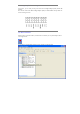
Before burning your firmware into the EMBER357, please make sure that all the cables of InSight Adapter (ISA3) are attached to the RF module according to the pin assignment mentioned earlier. Now select the firmware file with s37 extension that you wish to write. Click Upload Application, a similar software screen will appear as shown below: Click the button and go to the file. To write the firmware, simply click on .
The OEM integrator has to be aware of not to providing information to end users regarding how to install or remove this RF module in the user manual of the end product. The user manual which is provided by OEM integrators for end users must include the following information in a prominent location.
This page is left blank intentionally