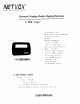
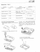
NETFLIX COMPUTERS & COMMUNICATIONS Numeric Display Radio Paging Receiver G-568 Pager 26 delectable alerts — Mute vibration and alerting sound ~ 17 digits LCD display Calendar — Message timekeeping 4 ID Codes 2 builtin alarm clocks Continuous message indication Manual illumination ~ 15 sets of memory retention ~-8 sets of memory protection Service area indication Error message correction Low battery alert Key in ID directly — Unread message reminder 6-568 POSTBAG PAGER Compact USER MANUAL
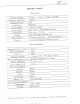
SPECIFICATIONS Characteristics Frequency Range 137MHz | MHz, 278MHz 284MHz Frequency Deflection 45K Hz | Modulation Tape i FSK Code Type POSTBAG ; Signaling Rate I 312BPS/1200BPS Power Supply [One “AAA” volition alkaline battery Dimensions 63 x 446% 17.
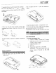
PRINCIPLE SUMMARY Code Format G-558 designs for compatibility with POSTBAG standard code { CIR radio paging code NO 13 Diagram 1 Process of Pager Receiving Diagram 2 RF Part Diagram 3 CPU Part RF Part Components oa Antenna One gold-pirated copper bars form a singe-loop antenna. The antenna circuitry is made up of L101, L102.
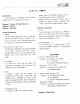
General Alf of the circuit is contained on one print circuit board, including RF and CPU circuit. All easy replacement and repair. PCB Equipment for Test { Table 1} REPAIR the PCB is designed for i No. I Equipment J Specification _ Purpose signal generator Frequency range | 100-180MHz . Check receiver | | Deviation" 0--kHz | i | Output level frequency counter ! Frequency range .
Repairing Tools {Table 2} Description item Ne, Remark Appearance i | Tweezers .
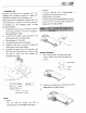
Assemble the push switch bracket, then emblem the PCB to the rabbet The * + "and * battery contacts should be vertically assemble to the rabbet of top cabinet. 8 Place the night side hook of bottom cabinet, then compress the left side. Screw the screw and other parts. Load the battery, assemble the battery compartment cover, ry | installation 1 Slide the battery cover stop and slide to lit battery cover 2 Pull the battery from the battery.
a Sensitivity Test Sensitivity is measured by field strength (bumf. The repeating test is essential condition for testing this specification. Sensitivity should be tested in the shield area that avoid interrupting by external noise. The value of sensitivity is a relative. It should be measured py compared tc a well operating pager. Tne test procedure as below 1) Connect the encoder output 10 external modulator pot of signal generator.
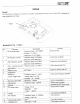
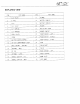
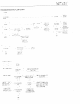
NINETY EXPLORED VIEW TEM PART NAME ren DART ANEW RESET TET: 2 ERIN 18 BATTERY CONTACT | =: Lo owe 1a BATTERY CONTACT [ Poa cue mer 20 HOLDER C5 CLIP SPRING 21 RE FLEXIBLE PAPER Ds oie speck 22 | RUBBER CONTACT 7 | Free PLATES 01 FUNCTION KEY LEFT) 8 sa | scion kev wins 5 BATTERY COVER STOPPER 25 FUNCTION KEY © RIGHT | 10 | BATTERY COMPARTMENT COVER 2% RING D0 mast cabinet © BOTTOM 27 CHAIN SHAFT 12 ANTENNA SHALL | CHAIN RF 208 < BASE CABINET [ TOP 74 | ANTENNA © LARGE © 30 BRASS SUPPORT 15 BUBBLE CUSHION °
PCB PARTS LIST QTV Camp-name PART-NAME L140 oa 101.102.203.304 : Gee 282404. 0455 25A11621G) 5 1 | PROTECT DIODE 3104 MATH 5 1 PN DIODE | C102 | 165314 T 4 : NATAL X01 J FR-21.4 02 MHZ UMS 5 : ITAL x1402 | 20 945MHZ : 209 2°9 5 i ITAL FILTER £304 : 21 MHZ. { UM-5 | 0 MIC FILTER Fag 455KIHZ (CRABWISE § td DISCRIMINATE SDBMASEC28 2 Loo | -coerces | 2-10P { TCO3CI00A 13 2 | Overcapacity_ 45-207 | TCO3C2004 | + ANTENNA | ! ANTENNA (BIG .
Comp-name CART-NAME SME CAPACITOR SME CAPACITOR 103213424 (B03 SMD CAPACITOR SME CA PACK 340.425 440 SMO CAPACITY C3 SMD CAPACITY DESCRIPTION 18P ( NPQ. ~~C. 257 ) 18P (NPQ ) 207 ( NPO" 22P (NPO 27P 1 NPD 33P NPD SOP 4 XTR: = 100CP { XTR, i-1C% ; 3300F { 0.