
User Manual


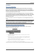


Table Of Contents

4
Installation
External Antenna Port Assignments
Use the following table and associated diagram to determine antenna port assignments
for each external antenna sensor model.
WLAN0 = 1st radio
WLAN1 = 2nd radio
Sensor Model
Port Assignments
SENSOR4-R1S0-E
P1-WLAN0-Ch0, P3-WLAN0-Ch1, P5-WLAN0-Ch2
SENSOR4-R1S1-E
P1-WLAN0-Ch0, P3-WLAN0-Ch1, P5-WLAN0-Ch2, P7-Spectrum
SENSOR4-R2S0-E
P1-WLAN0-Ch0, P3-WLAN0-Ch1, P5-WLAN0-Ch2, P4-WLAN1-Ch0,
P6-WLAN2-Ch1, P8-WLAN2-Ch2
SENSOR4-R2S1-E
P1-WLAN0-Ch0, P3-WLAN0-Ch1, P5-WLAN0-Ch2, P4-WLAN1-Ch0,
P6-WLAN2-Ch1, P8-WLAN2-Ch2,
P7-Spectrum