Netopia Router Reference Guide
Copyright Copyright © 1998 Netopia, Inc. v.298 All rights reserved. This manual and any associated artwork, software and product designs are copyrighted with all rights reserved. Under the copyright laws such materials may not be copied, in whole or part, without the prior written consent of Farallon Communications. Under the law, copying includes translation to another language or format. Netopia, Inc. 2470 Mariner Square Loop Alameda, CA 94501-1010 U.S.A.
Contents Chapter 1 — Introduction .......................................................... 1-1 How to use this guide .................................................... 1-2 Netopia models.................................................... 1-3 Connecting to the Advanced Configuration screens........... 1-4 Connecting a modem to the SmartPort ................... 1-4 Navigating through the Advanced Configuration screens ........................................................................
iv Reference Guide Readying computers on your local network....................... Connecting to a LocalTalk network— for 400 series models.................................................... Connecting to an Ethernet network.................................. EtherWave ........................................................... 10Base-T............................................................. Thick and Thin Ethernet ........................................
Contents v AppleTalk Setup for Small Office models.......................... 6-7 AppleTalk Setup for Corporate models ............................. 6-9 EtherTalk Setup.................................................... 6-9 LocalTalk Setup.................................................. 6-11 AURP setup ....................................................... 6-12 Chapter 7 — Security................................................................ 7-1 Suggested security measures ..........................
vi Reference Guide Establishing a dial-on-demand (DOD) connection call..................................................... 8-5 Establishing a manual connection call ................... 8-8 Troubleshooting ............................................................. 8-9 Chapter 9 — Monitoring Tools ................................................... 9-1 Status overview............................................................. 9-1 General Status.....................................................
Contents Uploading configuration files ............................. Transferring configuration and firmware files with TFTP .................................................................. Updating firmware ............................................ Downloading configuration files ......................... Uploading configuration files ............................. vii 10-16 10-17 10-18 10-19 10-20 Appendix A — Troubleshooting .................................................. Power outages .......
viii Reference Guide About SPIDs .................................................................. Example SPIDs .................................................... Second directory number ............................................... Switch-specific uses ............................................. Backup number.................................................... Dynamic B-channel usage............................................... Other incoming call restrictions .............................
1-1 Chapter 1 Introduction Your Netopia Router offers Advanced Configuration features in addition to the Easy Setup features. The advanced feature screens are accessed through the Main Menu of the Router’s console configuration screen. This Reference Guide documents the advanced features, including advanced testing, security, monitoring, and configuration features. This Reference Guide should be used as a companion to the Easy Setup configuration instructions in the Netopia Router Getting Started guide.
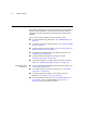
1-2 Reference Guide How to use this guide This guide is organized into chapters describing each of the Netopia Router’s advanced features. You may want to read each chapter’s introductory section to familiarize yourself with the various features available. You can also use this summary to locate relevant sections: 400 Netopia series models only ■ To configure ISDN setup parameters, see “ISDN WAN Setup” on page 2-2. ■ To configure leased line setup parameters, see “Leased line WAN Setup” on page 2-5.
Introduction 1-3 ■ For IP filters, see “About filters and filter sets” on page 7-6 and “Working with IP filters and filter sets” on page 7-16. ■ To transfer firmware and configuration files, see “Transferring configuration and firmware files with XMODEM” on page 10-12 or “Transferring configuration and firmware files with TFTP” on page 10-17. ■ To secure your network with SecurID, see Chapter 8, “Token Security Authentication.
1-4 Reference Guide Connecting to the Advanced Configuration screens There are three ways to connect to the Netopia Router’s advanced configuration screens: ■ Through the console port, using a local terminal (see the Getting Started Guide) ■ Using Telnet with the Router’s Ethernet port IP address (cannot be used for initial configuration) ■ Over analog phone lines using a modem and terminal emulation software (see “Connecting a modem to the SmartPort,” below) You can also retrieve the Netopia Router
Introduction 1-5 Follow the manufacturer’s instructions when unpacking and preparing to use the PC Card modem. One end of the telephone cable connects to your modem, while the other end (RJ-11) connects to an analog telephone line wall socket (not an ISDN or leased line). SmartPort PC Card (PCMCIA) To attach the modem to the Netopia Router, pull down the rubber door that covers its SmartPort slots and insert the modem. You can use either slot.
1-6 Reference Guide Navigating through the Advanced Configuration screens To help you find your way to particular screens, some sections in this guide begin with a graphical path guide similar to the following example: Main Menu Advanced Config. WAN Setup • ISDN Line Config. • Connection Profiles • Answer Profile This particular path guide shows how to get to the WAN Setup screens. The path guide represents these steps: 1.
Introduction 1-7 Keyboard navigation Use your keyboard to navigate the Netopia Router’s configuration screens, enter and edit information, and make choices. The following table lists the navigation keys. To... Use These Keys...
1-8 Reference Guide
2-1 Chapter 2 Configuring ISDN and Leased Line Connections This chapter shows you how to configure the Netopia Router to make and receive network connections over an ISDN or leased line and how to control those connections. Topics include: ■ “ISDN WAN Setup” on page 2-2 shows you how to configure your ISDN Netopia Router for outgoing calls. ■ “Leased line WAN Setup” on page 2-5 shows you how to configure your SA/Serial, DDS, or T1 Netopia Router for outgoing calls.
2-2 Reference Guide ISDN WAN Setup Main Menu Advanced Configuration • Line Configuration • Connection Profiles • Default Answer Profile WAN Setup The ISDN WAN Setup screen has three subscreens, each involving a different aspect of using the ISDN line to control connections to remote IP or IPX networks. Note: If you have completed Easy Setup (see the Getting Started Guide), the information you have already entered will appear in some of the Advanced Configuration screens.
Configuring ISDN and Leased Line Connections 2-3 Note: If your ISDN Line Configuration screen contains items that are not discussed in this section, such as SPIDs, see Appendix C, “ISDN Configuration Guide.” The ISDN Line Configuration screen consists of up to three pop-up menus and up to four editable fields. North America ISDN models only ISDN Line Configuration Circuit Type... Switched Switch Type... National ISDN-1 (NI-1) SPID 1: 510.238.4166.1 SPID 2: 510.238.4167.
2-4 Reference Guide ISDN Line Configuration Circuit Type... Permanent B-Channel Usage... B1 Data Link Encapsulation... PPP Enter information supplied to you by your ISDN phone company. From the pop-up menu, select the appropriate B-channel, such as B1, B2, or Both. Then go to step 7. Note: A permanent ISDN circuit type only supports 64 kbps and 128 kbps B-channel usages. 3. Select Switch Type and press Return. From the pop-up menu, select the switch protocol your ISDN service provider uses.
Configuring ISDN and Leased Line Connections 6. 2-5 Select Directory Number 1 and enter the primary directory number as you would dial it, including any required prefixes (such as area, access, and long-distance dialing codes). Press Return. Note: If you select an IDSL (Pt-to-Pt) switch, the Directory Number 1 field will default to 555-1234. Since an IDSL line is already physically hooked up in a pt-to-pt configuration, a specific directory number is not necessary.
2-6 Reference Guide WAN Setup Line Configuration... Frame Relay Configuration... Frame Relay DLCI Configuration... Connection Profiles... Default Profile... From here you will configure yours and the remote sites' WAN information. Note: For all leased line Netopia Router models using PPP or CiscoHDLC datalink encapsulation, the Frame Relay Configuration and Frame Relay DLCI Configuration options will be hidden.
Configuring ISDN and Leased Line Connections 2-7 The DDS Line Configuration screen appears for DDS leased line models (with an internal CSU/DSU connection). See page 2-12. Line configuration for an SA/Serial line The Serial Line Configuration screen is where you enter the configuration parameters for your leased line, in order for the Netopia Router to communicate with the physical connection.
2-8 Reference Guide Equipment) because their transmit data can become altered in relation to the clock sourced by the DCE (Data Communications Equipment). A DTE (Data Terminal Equipment) is a term used to define the equipment rate. It is a designation for the maximum rate at which a router can exchange information. A DCE (Data Communications Equipment) is a term defined by both Frame Relay and X.
Configuring ISDN and Leased Line Connections Switched async only 2-9 6. Select Date Rate (kbps) and press Return. From the pop-up menu, select 19.2, 38.4, 57.6, 115.2, or 230.4. Choose the data rate that is about twice your modem’s capabilities. For instance, if you have a 28.8K modem, select 57.6 for your data rate. Press Return. 7. The Modem Initialization String and Modem Dialing Prefix fields configure the connection to the external modem.
2-10 Reference Guide T1 Line Configuration Line Encoding... B8ZS Framing Mode... ESF Transmit ANSI PRMs: No Number of DS0 Channels: 1 First DS0 Channel: 1 Buildout (-dB)... Auto Channel Data Rate... Nx64k Clock Source... Network Data Link Encapsulation... Frame Relay Enter Information supplied to you by your telephone company. 1. Select Line Encoding and press Return. From the pop-up menu, highlight the encoding your telephone service provider uses: B8ZS or AMI.
Configuring ISDN and Leased Line Connections 2-11 Note: Each DS0 channel represents a 56k or 64k increment in bandwidth. Selecting a number less than the maximum of 24 specifies a fractional-T1 interface. For fractional-T1, you may also specify in the check box whether the DS0 channels are contiguous or alternating. 5. Select First DS0 Channel and enter the number of the first active DS0 channel you will be using. The default setting is 1 (one). Press Return.
2-12 Reference Guide Line configuration for a DDS line The DDS Line Configuration screen is where you enter the configuration parameters for your leased line, in order for the Netopia Router to communicate with the physical connection. Use the information in the Leased Line worksheet in the Getting Started Guide as a reference when specifying your DDS line configuration information. DDS Line Configuration Circuit Type... Permanent Data Rate... Auto Clock Source... Network Data Link Encapsulation..
Configuring ISDN and Leased Line Connections 2-13 3. Select Clock Source and press Return. From the pop-up menu, highlight the clock source, that you wish to use. The choices offered are Internal Clock Source, or Network Clock Source. The default is Network. Press Return. 4. Select Data Link Encapsulation and highlight the method of encapsulation that you want to use from the pop-up menu. The choices offered are PPP, HDLC, and Frame Relay. The default setting is Frame Relay. Press Return. 5.
2-14 Reference Guide Connection Profiles Display/Change Connection Profile... Add Connection Profile... Delete Connection Profile... Establish WAN Connection... Disconnect WAN Connection... Return/Enter to modify an existing Connection Profile. This Screen is the main point of navigation for Connection Profiles. Note: The Establish WAN Connection and Disconnect WAN Connection fields in the Connection Profiles screen will only appear for a Netopia Router model with switched circuit selected.
Configuring ISDN and Leased Line Connections 2-15 Connection Profiles +-Profile Name---------------------IP Address----IPX Network-+ +------------------------------------------------------------+ | Easy Setup Profile 127.0.0.2 | Panost Inc. 0.0.0.0 0 | | | XYZ Corporation 0.0.0.0 | +------------------------------------------------------------+ Up/Down Arrow Keys to select, ESC to dismiss, Return/Enter to Edit.
2-16 Reference Guide Deleting a Connection Profile To delete a connection profile, select Delete Connection Profile in the Connection Profiles screen and press Return to display a table of connection profiles. Connection Profiles +-Profile Name---------------------IP Address----IPX Network-+ +------------------------------------------------------------+ | Gunther Hydroelectric 127.0.0.
Configuring ISDN and Leased Line Connections 2-17 Add Connection Profile Profile Name: Profile 04 Profile Enabled: Yes IP Enabled: Yes IP Profile Parameters... IPX Enabled: Yes IPX Profile Parameters.. Data Link Encapsulation... PPP Data Link Options... Interface Group... Int CSU Telco Options... ADD PROFILE NOW Configure a new Conn. Profile. Finished? CANCEL ADD or CANCEL to exit. 1. Select Profile Name and enter a name for this connection profile. It can be any name you wish.
2-18 Reference Guide IP Profile Parameters Address Translation Enabled: Yes IP Addressing... Numbered Local WAN IP Address: 0.0.0.0 Local WAN IP Mask: 0.0.0.0 Remote IP Address: 0.0.0.0 Remote IP Mask: 0.0.0.0 Filter Set... Remove Filter Set Receive RIP: Yes Configure IP requirements for a remote network connection here. Applicable only to SmartIP models 5. In the IP Profile Parameters screen, toggle Address Translation Enabled to Yes if you choose to use Network Address Translation.
Configuring ISDN and Leased Line Connections 2-19 The default address for the Local WAN IP Address is 0.0.0.0, which allows for dynamic addressing, when your ISP assigns an address each time you connect. However, you may enter another address if you want to use static addressing. Note: When using Cisco-HDLC datalink encapsulation and Network Address Translation, you must use a static address.
2-20 Reference Guide a WAN IP address or subnet mask associated with this connection. These default addresses will request that the remote router dynamically assign an address at the time the connection is made. To configure a profile for a terminal adapter or Netopia Router that is dialing into your router using dynamic Network Address Translation, you may enter a 0.0.0.0 remote IP address and enable IP WAN Address Serving.
Configuring ISDN and Leased Line Connections 2-21 Note: Using the IPX protocol is required with other remote networks using IPX for an intranet connection. For more information on IPX, refer to Chapter 5, “IPX Setup” of this guide. ■ Select IPX Profile Parameters and press Return. This option is only available if IPX Enabled is toggled to Yes. IPX Profile Parameters Remote IPX Network: 00000000 Path Delay: 10 NetBios Packet Forwarding: Off Incoming Packet Filter Set...
2-22 Reference Guide ■ To change the default Path Delay, select and enter a value (in ticks). ■ To enable NetBIOS Packet Forwarding, toggle the selection to Yes. ■ Select Incoming Packet Filter Set to attach a filter set for filtering incoming packets. Choose a filter set from the list and press Return. ■ Select Outgoing Packet Filter Set to attach a filter set for filtering outgoing packets. Choose a filter set from the list and press Return.
Configuring ISDN and Leased Line Connections 2-23 Point-to-Point Protocol (PPP) and Multilink Point-to-Point Protocol (MP) allow the Netopia Router to make adaptable and secure connections to other networks. PPP/MP Options Data Compression... Ascend LZS Send Authentication... PAP Send User Name: Send Password: Receive User Name: Receive Password: B-Channel Usage... Dynamic BAP Usage... Off Return/Enter to choose PPP Authentication type (or None).
2-24 Reference Guide authentication is set for PAP, as this is usually the most popular security parameter that ISP’s and other remote networks set up for a point-to-point connection use. ■ If you choose None, and the remote network expects to connect to the Netopia Router using this connection profile, you may need to set the answer profile to accept calls using no authentication (None). See “Default profile” on page 2-39.
Configuring ISDN and Leased Line Connections ■ 2-25 If you choose to use CACHE-TOKEN, select Send User Name and enter a name for your Netopia Router. Then, select Send Password and enter a secret name or number. If you will be using SecurID (an added method of security authentication), check with your network administrator to find out if you will need to use either PAP-TOKEN, or CACHE-TOKEN. (Also, see Chapter 9, “Security-Token Authentication”.) PPP/MP Options Data Compression...
2-26 Reference Guide accept an incoming call through or when a second connection profile is used to make a call. See Appendix D for information on “Dynamic B-channel usage”. ■ 1 B-Channel forces a call to remain within one B-channel. (Throughput will generally be at either 56k or 64k, depending on how the local telephone company installs your ISDN line. This will also depend on certain geographic locations in North America. The standard ISDN data rate outside of North America is 64k.
Configuring ISDN and Leased Line Connections 2-27 telephone number for a multilink call. In addition, the Netopia Router can bring WAN links up and down with a remote router. Note: There are two specifications for BAP protocol. The first specification was proposed before January 1997 and the latter was proposed after that date. The On-Old IDs selection refers to the earlier BAP proposal and On-New IDs refer to the new proposal.
2-28 Reference Guide T1 and DDS models only 10. The Interface Group field reflects the active port selection: the internal CSU for T1 or DDS, or SA port for SA, if backup is enabled. See “CSU Backup” on page 2-55 for more information. Models with Switched circuits only 11. Select Telco Options and press Return. The Telco Options screen appears. The Telco Options screen contains items that allow you to control the calls made on the WAN line with this particular connection profile.
Configuring ISDN and Leased Line Connections 2-29 ■ Select Dial and set this connection profile to only make calls, only receive calls, or do both. Choose from In Only (receive calls), Out Only (make calls), or Dial In/Out (receive and make calls). ■ Select Number to Dial and enter the telephone number you received from your ISP. This is the number the Netopia Router dials to reach your ISP.
2-30 Reference Guide ISDN Switched circuit models only ■ The CNA Validation Number is the telephone number that your Netopia Router will match to incoming calls. Question marks “?” can be used in place of numbers as wild card characters to ensure that matches are made on different directory numbers. See “Default profile” on page 2-39 for information on CNA (Calling Number Authentication).
Configuring ISDN and Leased Line Connections 2-31 If a connection is establishing properly, the Connection State will initially read Acquiring but will change to Up once the call has successfully connected. You will be able to access information at the remote site that you are connecting to once authentication is completed successfully.
2-32 Reference Guide Frame Relay Configuration LMI Type... ANSI (Annex D) T391 (Polling Interval in secs): 10 N391 (Polls/Full Status Cycles): 6 N392 (Error Threshold): 3 N393 (Monitored Event Window): 4 Tx Injection Management... Standard Default CIR: 64000 Default Bc: 64000 Default Be: 0 Congestion Management Enabled: Yes Maximum Tx Frame Size: 1536 Enter Information supplied to you by your telephone company. 1. Select LMI Type (Link Management Type) and press Return.
Configuring ISDN and Leased Line Connections 2. 2-33 ■ The N392 option specifies the maximum number of (link reliability, protocol, and sequence number) error events that can occur within the N393 sliding window. If an N392 threshold is exceeded, the switch declares the Netopia Router inactive. The default setting is 3. ■ The N393 option allows the user to specify the width of the sliding N392 monitored event window. The default setting is 4. Select Tx Injection Management and press Return.
2-34 Reference Guide ■ The Default Be (Be also referred to as Excess Burst Size) represents the maximum amount of data that your Frame Relay service provider will attempt to deliver to a given PVC (Permanent Virtual Circuit) or DLCI (Data Link Connection Identifier). This setting defaults to 0, but you may change the capacity rate if this setting needs to be modified. See Appendix B, “Understanding Frame Relay” in the Getting Started Guide for information on the these parameters.
Configuring ISDN and Leased Line Connections 2-35 A Frame Relay DLCI is a set of parameters that tells the Netopia Router how to initially connect to a remote destination. The Netopia Router leased line models support up to 16 different Frame Relay DLCI configuration profiles. Each Frame Relay DLCI configuration you set up allows the Netopia Router to connect your network to another network that uses IP or IPX over Frame Relay.
2-36 Reference Guide Changing a Frame Relay DLCI configuration To modify a Frame Relay DLCI configuration, select Display/Change DLCIs in the Frame Relay DLCI Configuration screen. Select a DLCI Name from the table and press Return to go to the Change DLCI screen. The parameters in this screen are the same as the parameters in the Add DLCI screen. To find out how to set them, see “Adding a Frame Relay DLCI configuration” on page 2-37.
Configuring ISDN and Leased Line Connections 2. 2-37 A Frame Relay DLCI Configuration table appears with a prompt asking you if you want to delete the connection profile you have just highlighted. Select CONTINUE if you wish to delete this DLCI or CANCEL if you do not. You are now done configuring the Frame Relay DLCI Configuration screen. Press the escape key to return to the WAN Setup screen.
2-38 Reference Guide Note: The Netopia Router allows Frame Relay DLCIs to be named, so that you can easily reference and differentiate them. This is accomplished by giving a DLCI Name to a DLCI Number. Frame Relay DLCI Configuration +-DLCI Name----------DLCI Number-+ +--------------------------------+ | Panost Inc. 16 | | THARPER Inc. 32 | | | +--------------------------------+ Up/Down Arrow Keys to select, ESC to cancel, Return/Enter to Delete. 2.
Configuring ISDN and Leased Line Connections 2-39 ■ The Bc (Committed Burst Size) represents the maximum amount of data that your Frame Relay service provider agrees to transfer from a given PVC (Permanent Virtual Circuit) or DLCI (Data Link Connection Identifier). The setting defaults to 64000, but you may modify the committed burst size by toggling the selection in the Use Default field to No. You can then enter a different committed burst size in the Value field.
2-40 Reference Guide How the default profile works for a switched circuit The Default Profile works like a guard booth at the gate to your network: it scrutinizes incoming calls. Like the guard booth, the default profile allows calls based on a set of criteria that you define. The main criterion used to check calls is whether they match one of the connection profiles already defined.
Configuring ISDN and Leased Line Connections 2-41 WAN Setup Line Configuration... Connection Profiles... Default Answer Profile... From here you will configure yours and the remote sites' WAN information. 1. Select Default Answer Profile in the WAN Setup screen. Press Return. The Default Profile screen appears. 2.
2-42 Reference Guide Note: If the actual calling number and entered calling number do not have the same number of digits, CNA can still match the numbers. The smaller number determines how many digits must match. For instance, if the actual calling number is 10 digits and the entered calling number is 7 digits, only 7 digits must be matched. The 7 digits that must be matched in this example are the last 7 digits of each calling number.
Configuring ISDN and Leased Line Connections 2-43 Note: For an ISDN switched circuit with HDLC datalink encapsulation enabled, the Default Profile screen will only show the Calling Number Authentication pop-up menu. 3. To force incoming calls to match connection profiles, select Must Match a Defined Profile and toggle it to Yes. Incoming calls that cannot be matched to a connection profile are dropped.
2-44 Reference Guide words, you will have to set up a connection profile for that network.
Configuring ISDN and Leased Line Connections 2-45 How the default profile works for a permanent circuit The default profile works like a guard booth at the gate to your network: it scrutinizes WAN connections. Like the guard booth, the default profile allows connections based on a set of criteria that you define. The main criterion used to check connections is whether they match one of the connection profiles already defined.
2-46 Reference Guide Customizing the default profile You can customize the Netopia Router’s default frame relay profile in the Default Frame Profile screen. WAN Setup Line Configuration... Frame Relay Configuration... Frame Relay DLCI Configuration... Connection Profiles... Default Frame Profile... Return/Enter for default WAN connection parameters. 1. Select Default Frame Profile in the WAN Setup screen. Press Return. The Default Frame Profile screen appears.
Configuring ISDN and Leased Line Connections 2-47 If Must Match a Defined Profile is set to No, you can also set the following parameters for accepted calls that do not match a connection profile: ■ Network Address Translation ■ Interface-based Routing or System-based Routing ■ Firewall Filter Set ■ Transmit RIP ■ Receive RIP ■ TX RIP Policy to use either Split Horizon or Poison Reverse ■ Net BIOS Packet Forwarding ■ Net BIOS Path Delay ■ Periodic RIP Timers ■ Periodic SAP Timers Call
2-48 Reference Guide ■ ■ To allow calls that only match a connection profile’s remote IP and/or IPX address: ■ Toggle Must Match a Defined Profile to Yes, and ■ set Authentication to None. To not allow any incoming calls to connect to the Netopia Router: ■ Toggle Must Match a Defined Profile to Yes, and ■ Set the Dial option in the Telco Options screen of every connection profile to Dial Out Only WAN IP Address Serving Main Menu Small Office ISDN models only Advanced Config.
Configuring ISDN and Leased Line Connections 2-49 IP Address Serving IP Address Serving: On Server Name is Netopia PN435 To select WAN IP Address Serving, go to the IP Address Serving screen from the Advanced Configuration menu and toggle On. Note: WAN IP Address Serving is used for only incoming caller connections. Refer to “IP address serving” on page 4-16, for more information on how to use WAN IP Address Serving. Scheduled connections Main Menu Advanced Config.
2-50 Reference Guide Viewing scheduled connections To display a table of view-only scheduled connections, select Display/Change Scheduled Connection in the Scheduled Connections screen. Each scheduled connection occupies one row of the table. Scheduled Connections +-Days ---- Begin At - HH:MM--- When ----- Conn. Prof.
Configuring ISDN and Leased Line Connections 2-51 Adding a scheduled connection To add a new scheduled connection, select Add Scheduled Connection in the Scheduled Connections screen and go to the Add Scheduled Connection screen. Add Scheduled Connection Scheduled Connection Enable: On How Often... Weekly Schedule Type... Forced Set Weekly Schedule... Use Connection Profile...
2-52 Reference Guide Demand-Blocked defines the schedule when demand calls are prevented. ■ If you selected Weekly, select Set Weekly Schedule and go to the Set Weekly Schedule screen. ■ Select the days for the scheduled connection to occur and toggle them to Yes. Set Weekly Schedule Monday: No Tuesday: No Wednesday: No Thursday: No Friday: No Saturday: No Sunday: No Scheduled Window Start Time: ■ 02:08 AM or PM: PM Call Window Duration: 00:00 Every ... 15 min.
Configuring ISDN and Leased Line Connections 2-53 ■ Select AM or PM and choose AM or PM from the pop-up menu. ■ Select Scheduled Window Duration and enter the maximum duration allowed for this scheduled window (not for the call). ■ If you selected Periodic, select Every and choose how often the call should be attempted. The default is every 15 minutes. You are done configuring the weekly options. Return to the Add Scheduled Connection screen to continue.
2-54 Reference Guide ■ Select AM or PM and choose AM or PM. The AM or PM item appears only if the time is in the 12-hour clock format. ■ Select Scheduled Window Duration and enter the maximum duration allowed for this scheduled window (not for the call). Use the same format restrictions noted above. You are done configuring the once-only options. Return to the Add Scheduled Connection screen to continue.
Configuring ISDN and Leased Line Connections 2-55 CSU Backup Main Menu Advanced Configuration WAN Setup CSU Backup Configuration When you are using the leased line interfaces T1 and DDS, you can configure an automatic CSU backup, to switch to the SA port during a leased line failure. CSU Backup Configuration Enable SA Port as CSU Backup Yes Requires Data Link Failure of... 30 Sec Circuit Type... Switched Async Data Rate (kbps)... 57.
2-56 Reference Guide
3-1 Chapter 3 Connecting Your Local Network In this chapter, you will learn how to physically connect the Netopia Router to your local area network (LAN). Before you proceed, make sure the Netopia Router is properly configured. You can configure the Router using Console-based Management or Web-based Management (see the Getting Started Guide). Overview You can connect the Netopia Router to an IP or IPX network that uses Ethernet.
3-2 Reference Guide See the sections later in this chapter for details on how to connect the Netopia Router to the two types of networks. Readying computers on your local network PC and Macintosh computers must have certain components installed before they can communicate through the Netopia Router. The following illustration shows the minimal requirements for a typical PC or Macintosh computer.
Connecting Your Local Network 3-3 EtherTalk and LocalTalk: These are AppleTalk protocols used over Ethernet. Once the Netopia Router is properly configured and connected to your LAN, PC and Macintosh computers that have their required components in place will be able to connect to the Internet or other remote IP networks. Connecting to a LocalTalk network—for 400 series models Connect one end of the LocalTalk cable to the Netopia Router’s PhoneNET port.
3-4 Reference Guide Connecting to an Ethernet network The Netopia Router supports an Ethernet connection to either its AUI or its EtherWave ports. The Router’s autosensing feature eliminates the need for a switch; connection to the AUI or EtherWave ports is automatically detected and the connected port is used. You can connect several types of Ethernet networks to the Netopia Router. Most are distinguished by the type of cable they use.
Connecting Your Local Network 3-5 EtherWave To add the Netopia Router to your EtherWave daisy chain, use a 10Base-T cable with RJ-45 connectors. The router can be connected to your EtherWave network at any point in the daisy chain.
3-6 Reference Guide You may use either or both of the EtherWave ports to connect the Netopia Router, as needed. No termination is necessary, even when the router is at the end of your EtherWave network.
Connecting Your Local Network 3-7 10Base-T You can connect a 10Base-T Ethernet network to the Netopia Router either through one of its EtherWave ports or through its AUI port. EtherWave 10Base-T HUB The Netopia Router in a 10Base-T network To connect your 10Base-T network to the Netopia Router through its EtherWave port, use a 10Base-T cable with RJ-45 connectors. You may connect your 10Base-T network to either EtherWave port.
3-8 Reference Guide Thick and Thin Ethernet You can connect a 10Base-5 (Thick Ethernet) or 10Base-2 (Thin Ethernet) network to the Netopia Router’s AUI port. To connect your 10Base-5 network to the Netopia Router’s AUI port, use a standard Ethernet 10Base-5 transceiver and cable. To connect your 10Base-2 network to the Netopia Router’s AUI port, use a standard Ethernet 10Base-2 transceiver and cable.
4-1 Chapter 4 IP Setup The Netopia Router uses Internet Protocol (IP) to communicate both locally and with remote networks. This chapter shows you how to configure the Router to effectively route IP traffic. You also learn how to configure the Router to serve IP addresses to hosts on your local network. Some models of the Netopia Router support the SmartIP feature, which includes Network Address Translation (NAT).
4-2 Reference Guide ■ The single proxy address is acquired at connection time from the answering side. The address can be assigned by the remote router from either a dynamic pool of addresses or a fixed, static address. ■ Static NAT (Network Address Translation) Security is made simpler and more reliable by only having to firewall one IP address and by obscuring the internal network structure from the Internet. Using NAT Follow these steps to use NAT. 1.
IP Setup 4-3 In the following example screen, 192.163.100.6 is assigned to the calling Netopia Router. Note: The QuickView screen varies by your Netopia Router model and line type. Quick View Ethernet Address - 00-00-c5-ff-60-8d Firmware Version -- Current Date - 5/31/97 03:09:43PM 3.0 IP Address - 163.176.8.
4-4 Reference Guide Associating port numbers with nodes When an IP client, such as a Netscape or Microsoft Internet Explorer web browser, wants to establish a session with an IP server, such as a web server, the client must know the IP address to use and the IP port where the traffic is to be directed. Just as an IP address specifies a particular computer on a network, ports are addresses that specify a particular service in a computer.
IP Setup 4-5 NAT guidelines Observe the following guidelines when using Network Address Translation. ■ The router can export just one local IP address per TCP port, so you can have just one machine available for a given service, such as one FTP server. However, some services, such as Web servers (www-http servers), allow you to change the TCP port on both the server and client. With two different TCP ports exported, you can have Web servers on two different IP hosts.
4-6 Reference Guide IP setup Main Menu Advanced Configuration Network Protocols Setup General IP Setup IP Options The IP Setup options screen is where you configure the Ethernet side of the Netopia Router. The information you enter here controls how the Router routes IP traffic.
IP Setup Small Office models only 4-7 IP Setup Ethernet IP Address: 192.168.6.137 Ethernet Subnet Mask: 255.255.255.248 Default IP Gateway: 0.0.0.0 DNS Server: 0.0.0.0 Secondary DNS Server: 0.0.0.0 Domain Name: Exported Services... Follow these steps to configure IP Setup for your Small Office Netopia Router: ■ Select Ethernet IP Address and enter the IP address for the Netopia Router’s Ethernet port.
4-8 Reference Guide Models supporting SmartIP only ■ If a secondary DNS server is available, select Secondary DNS Server and enter its IP address. The secondary DNS server is used by the Netopia Router when the primary DNS server is inaccessible. Entering a secondary DNS is useful but it is not necessary. ■ Select Domain Name and enter your network’s domain name (for example, farallon.com). Entering a Domain Name is strongly recommended. ■ Select Exported Services.
IP Setup ■ 4-9 Select Service. A pop-up menu of services and ports appears. Add Exported Service +-Type------Port-+ +----------------+ Service... Local Server's IP Address: ADD EXPORT NOW | ftp 21 | | telnet 23 | | smtp 25 | | tftp 69 | | gopher 70 | | finger 79 | | www-http 80 | | pop2 109 | | pop3 110 | | snmp 161 | | chat 531 | | Other... | +----------------+ CANCEL Select any of the services/ports and press Return to associate it with the address of a server on your local area network.
4-10 Reference Guide Non-Small Office models only IP Setup Ethernet IP Address: 192.168.6.137 Ethernet Subnet Mask: 255.255.255.248 Default IP Gateway: 0.0.0.0 DNS Server: 0.0.0.0 Secondary DNS Server: 0.0.0.0 Domain Name: Receive RIP: Off Transmit RIP: Off Static Routes... Set up the basic IP attributes of your Netopia in this screen.
IP Setup 4-11 ■ Select DNS Server and enter the IP address for a domain name server. The domain name server matches the alphabetic addresses favored by people (for example, www.netopia.com) to the IP addresses actually used by IP routers (for example, 163.7.8.202). ■ If a secondary DNS server is available, select Secondary DNS Server and enter its IP address. The secondary DNS server is used by the Netopia Router when the primary DNS server is inaccessible.
4-12 Reference Guide Static routes are helpful in situations where a route to a network must be used and other means of finding the route are unavailable. For example, static routes are useful when you cannot rely on RIP. To go to the Static Routes screen, select the Static Routes item in the IP Setup screen. Static Routes Display/Change Static Route... Add Static Route... Delete Static Route... Configure/View/Delete Static Routes from this and the following Screens.
IP Setup 4-13 Next Gateway: The IP address of the router that will be used to reach the destination network. Priority: An indication whether the Netopia Router will use the static route when it conflicts with information received from RIP packets. Enabled: An indication whether the static route should be installed in the IP routing table. Adding a static route To add a new static route, select Add Static Route in the Static Routes screen and go to the Add Static Route screen.
4-14 Reference Guide ■ Select Destination Network Subnet Mask and enter the subnet mask used by the destination network. ■ Select Next Gateway IP Address and enter the IP address for the router that the Netopia Router will use to reach the destination network. This router does not necessarily have to be part of the destination network, but it must at least know where to forward packets destined for that network. ■ Select Route Priority and choose High or Low.
IP Setup 4-15 Modifying a static route To modify a static route, select Display/Change Static Route in the Static Routes screen to display a table of static routes. Select a static route from the table and go to the Change Static Route screen. The parameters in this screen are the same as the ones in the Add Static Route screen (see “Adding a static route” on page 4-13).
4-16 Reference Guide ■ The connection profile associated with the static route has a disabled dial-on-demand setting, and there is no current connection using that connection profile. A static route is already installed in the IP routing table will be removed if any of the conditions listed above become true for that static route. However, an enabled static route is automatically reinstalled once the conditions listed above are no longer true for that static route.
IP Setup 4-17 ■ The third protocol, called IPCP, is part of the PPP/MP suite of wide area protocols used for ISDN WAN connections. It allows remote terminal adapters and NAT-enabled routers to be assigned a temporary IP address for the duration of their connection. ■ The fourth protocol, called MacIP, is used only for computers on AppleTalk networks. MacIP provides a protocol translation (or gateway) function between IP and AppleTalk as well as an IP address assignment mechanism.
4-18 Reference Guide Follow these steps to configure IP Address Serving: ■ Server Name is lists the Netopia Router’s name, model number and individual serial number. It is filled in automatically. ■ To serve IP addresses to clients, select IP Address Serving and toggle it to Yes. Activating IP Address Serving automatically enables DHCP, WAN clients, and dynamic MacIP/KIP clients (if you have an AppleTalk model).
IP Setup 4-19 DHCP Options Serve Domain Name: Yes Domain Name: Serve Default Gateway: Yes Default Gateway: 192.168.6.137 Serve DNS Servers: Yes Primary DNS Server IP Addr.: 163.176.4.10 Secondary DNS Server IP Addr.: 0.0.0.0 The DHCP Options screen offers a set of parameters that can be passed to each client requesting an IP address. These additional parameters simplify each client’s setup. ■ Select Serve Domain Name, toggle to Yes, and press Return.
4-20 Reference Guide ■ In the Secondary DNS Server IP Address menu item, the Secondary DNS Server IP Address will be automatically generated from the connection profile screen, if an address has been entered. (A secondary DNS IP address is not required, but may be helpful. For instance, if the Netopia Router attempts to communicate to the primary DNS but it is unavailable, then it will attempt to communicate with the secondary DNS.
IP Setup 4-21 DHCP NetBios Options Serve NetBios Type: Yes NetBios Type... Type B Serve NetBios Scope: No NetBios Scope: Serve NetBios Name Server: No NetBios Name Server IP Addr: 0.0.0.0 DHCP allows you to allocate IP Addresses dynamically. ■ To serve DHCP clients with the type of NetBIOS used on your network, select Serve NetBIOS Type and toggle it to Yes. ■ From the NetBIOS Type pop-up menu, select the type of NetBIOS used on your network.
4-22 Reference Guide You are now finished setting up DHCP NetBIOS Options. To return to the IP Address Serving screen press the Escape key once. ■ To enable BOOTP’s address serving capability, select Serve BOOTP Clients and toggle to Yes. Note: Addresses assigned through BOOTP are permanently allocated from the IP Address Serving pool. To release these addresses, toggle Serve BOOTP Clients to No and restart your Netopia Router.
IP Setup Non-Small Office AppleTalk models only ■ 4-23 Select MacIP/KIP Static Options and press Return. The MacIP (KIP) Forwarding Setup screen tells the Netopia Router how many static addresses to allocate for MacIP/KIP clients. The addresses must fall within the address pool from the previous screen. You will need to enter the number of static MacIP addresses to reserve in this screen. Note that the address pool IP range will also be listed for your referral in this screen.
4-24 Reference Guide
5-1 Chapter 5 IPX Setup Internetwork Packet Exchange (IPX) is the network protocol used by Novell NetWare networks. This chapter shows you how to configure the Netopia Router for routing data using IPX. You also learn how to configure the router to serve IPX network addresses.
5-2 Reference Guide Internetwork Packet Exchange (IPX) IPX is a datagram, connectionless protocol that Novell adapted from Xerox Network System’s (XNS) Internet Datagram Protocol (IDP). IPX is dynamically routed, and the routing architecture works by “learning” network addressing automatically. IPX address An IPX address consists of a network number, a node number, and a socket number. An IPX network number is composed of eight hexadecimal digits.
IPX Setup 5-3 Routing Information Protocol (RIP) RIP, which was also derived from XNS, is a protocol that allows for the bidirectional transfer of routing tables and provides timing information (ticks), so that the fastest route to a destination can be determined. IPX routers use RIP to create and dynamically maintain databases of internetwork routing information. See the last section in this chapter for more information on routing tables.
5-4 Reference Guide NetBIOS NetBIOS is a protocol that performs tasks related to the Transport and Session layers of the OSI model. It can operate over IPX, using a special broadcast packet known as “IPX Packet type 20” to communicate with IPX NetBIOS servers. IPX Spoofing Applicable only to ISDN switched lines The Netopia has several IPX features designed to restrict the traffic on the ISDN link when the unit is not sending or receiving IPX data.
IPX Setup 5-5 To go to the IPX Setup screen, from the Main Menu select Advanced Configuration and then select Network Protocols Setup and then select IPX Setup. Note: If you have completed Easy Setup, the information you have already entered will appear in the IP Setup options screen. IPX Setup IPX Routing: On Ethernet Encapsulation... 802.3 Ethernet Network Address: 00000000 Ethernet Path Delay: 1 Ethernet NetBios Forwarding: No Ethernet Inbound SAP Filter Set...
5-6 Reference Guide 4. To change the default path delay, select Ethernet Path Delay and enter a value (in ticks). This value is used to determine the port cost of using the Ethernet port in IPX RIP calculations. 5. To enable NetBIOS packet forwarding, select Ethernet NetBIOS Forwarding and toggle it to Yes. This parameter will determine whether “IPX Packet type 20” packets are forwarded on the Ethernet interface. These packets are used by NetBIOS and some other applications. 6.
IPX Setup 5-7 IPX in the answer profile The answer profile can be configured to accept calls from remote IPX networks. To configure the answer profile to accept calls from remote IPX networks, go to the Default Answer Profile screen. Note: The Default Answer Profile screen varies according to configuration. Default Answer Profile Authentication... None Force 56k on Answer: No Max. Receive Packet Size: 1500 Stac Data Compression... None Must Match a Defined Profile: No B Channel Usage...
5-8 Reference Guide IPX Parameters (Default Answer Profile) NetBios Packet Forwarding: Off Incoming Packet Filter Set... Outgoing Packet Filter Set... Incoming SAP Filter Set... Outgoing SAP Filter Set... Detach Filter Sets... Periodic RIP Timer: 60 Periodic SAP Timer: 60 Configure IPX values to use when no matching Profile can be found. IPX filters Main Menu Advanced Config. Filter Sets (Firewalls) IPX Filters and Filter Sets IPX packet filters work very similarly to IP packet filters.
IPX Setup 5-9 Setting up and using IPX filter sets is a four-step process: 1. Create the filters to use. 2. Create the filter sets to use. 3. Add filters to the filter sets. 4. Attach the filter sets to the answer profile or to connection profiles. You can configure IPX filters and set up IPX filter sets from the IPX Filters and Filter Sets screen. IPX Filters and Filter Sets Show/Change IPX Packet Filters... Add IPX Packet Filter... Delete IPX Packet Filter... Show/Change IPX Packet Filter Sets..
5-10 Reference Guide IPX packet filters For each IPX packet filter, you can configure a set of parameters to match on the source or destination attributes of IPX data packets coming from or going to the WAN. Viewing and modifying packet filters To display a view-only table of IPX packet filters, select Show/Change IPX Packet Filters in the IPX Filters and Filter Sets screen. To modify any of the filters in the table, note the desired filter and press Return to go to the Change Packet Filter screen.
IPX Setup 5-11 By default, the filter’s socket numbers and network and node addresses are null (all zeros). This sets the filter to match on any IPX data packet. You should configure the filter using criteria that meet your security needs. 1. Select Filter Name and enter a descriptive name for the filter. 2. To specify a source network for the filter to match on, select Source Network and enter an IPX network address. 3.
5-12 Reference Guide Viewing and modifying packet filter sets To display a table of IPX packet filter sets, select Show/Change IPX Packet Filter Sets in the IPX Filters and Filter Sets screen. To modify any of the filter sets in the list, select the desired filter set and press Return to go to the Change Packet Filter Set screen. The parameters in this screen are the same as the ones in the Add Packet Filter Set screen (see the next section).
IPX Setup 5-13 Show Filters/Change Actions on Match Filter Name---------------------Forward Filter 1 No Filter 2 No <> Yes Set whether filters forward or drop matching packets here. Select a filter and toggle the packet forwarding action to Yes (pass) or No (discard). 3. To add a filter to the filter set, select Append Filter to display a table of filters. Select a filter from the table and press Return to add it to the filter set.
5-14 Reference Guide IPX SAP filters For each IPX SAP filter, you can configure a set of parameters to match on certain attributes of IPX SAP packet entries. The filters check IPX SAP packets for entries that match and then act on those entries. The SAP packets themselves are always allowed to continue after their entries are checked. The purpose of filtering SAP packets is not to make your network more secure, but to add efficiency to network bandwidth use.
IPX Setup 5-15 Add SAP Filter Filter Name: Server Name: Socket: 0000 Type: 0000 IPX Network: 00000000 IPX Node Address: 000000000000 ADD FILTER NOW Configure a new IPX SAP Filter. Finished? CANCEL ADD or CANCEL to exit. By default, the filter’s socket and type numbers and network and node addresses are null (all zeros). This sets the filter to match on any IPX SAP packet entry. You should configure the filter using criteria that meet your needs.
5-16 Reference Guide 6. To specify an IPX node address for the filter to match on, select IPX Node Address and enter an IPX node address. 7. Select ADD FILTER NOW to save the current filter. Select CANCEL to exit the Add SAP Filter screen without saving the new filter. Deleting a SAP filter To delete a SAP filter, select Delete IPX SAP filter in the IPX Filters and Filter Sets screen to display a table of filters. Select a filter from the table and press Return to delete it.
IPX Setup 5-17 Add SAP Filter Set Filter Set Name: Show Filters/Change Action on Match... Append Filter... Detach Filter... ADD FILTER SET NOW CANCEL Modify an IPX SAP filter here. Changes are immediate. Follow these steps to configure the new SAP filter set: 1. Select Filter Set Name and enter a descriptive name for the filter set. 2.
5-18 Reference Guide 3. To add a filter to the filter set, select Append Filter to display a table of filters. Select a filter from the table and press Return to add it to the filter set. The default action of newly added filters is to not forward (discard) packet entries that match their criteria. To exit the table without adding the filter, press the Escape key. 4. To remove a filter from the filter set, select Detach Filter to display a table of appended filters.
IPX Setup 5-19 IPX routing tables Main Menu Statistics, Utilities, Tests Routing Tables • IPX Routing Table • IPX SAP Bindery Table IPX routing tables provide information on current IPX routes and services. To go to the IPX Routing Table screen, select IPX Routing Table in the Routing Tables screen. This table shows detailed information about current IPX network routes.
5-20 Reference Guide
6-1 Chapter 6 AppleTalk Setup This chapter discusses the concept of AppleTalk routing and how to configure AppleTalk Setup for a Netopia Router with AppleTalk capability. AppleTalk is available on the Netopia Router’s 400 series which includes both the Small Office and Corporate models. This chapter will discuss both versions. Skip this chapter if this information does not apply to your particular Netopia model.
6-2 Reference Guide Each computer or peripheral device (printer, client, file server) connected to a network is called a node and has a unique node address, which can be any number from 1 to 254. Whenever you open the Chooser or any application that communicates with other computers on your network, your application compiles a list of all node names and addresses.
AppleTalk Setup 6-3 To make the services on an internet manageable, groups of devices on a network can be grouped into zones. When this is done, selecting a network service (server, etc.) includes choosing a zone from which the service can be selected. Like network numbers, zone names are assigned by routers. A routing table is maintained by each AppleTalk router. The table serves as a map of the internet, specifying the path and distance, in hops, between its router and other networks.
6-4 Reference Guide A router has multiple communications ports and is capable of forwarding information to other routers and devices on the internet. The router performs packet forwarding, network and device address maintenance, and other administrative functions required by the AppleTalk protocols. The distinction between routers and bridges is an important one: ■ A true bridge, like a router, is used to join two cable segments and filter traffic between them.
AppleTalk Setup 6-5 When two networks using AppleTalk communicate with each other through a network based on the Internet Protocol, they are said to be tunneling through the IP network. The Netopia Router uses AURP to allow your AppleTalk network to tunnel to designated AppleTalk partner networks, as well as to accept connections from remote AppleTalk networks tunneling to your AppleTalk LAN. Routers and seeding To configure AppleTalk networks, you must understand the concept of seeding.
6-6 Reference Guide Soft seeding: When a router that uses soft seeding is turned on or reset, it requests network number and zone name information from any existing routers on the networks it will serve. If no other routers reply, the router uses the network numbers and zone names specified in its own configuration. If other routers reply, the router uses the information they provide, regardless of whether or not there are conflicts between the information received and its configured information.
AppleTalk Setup ■ 6-7 If you want the Netopia Router and all other routers on your network to use only their own configurations, set the Netopia Router and all other routers to hard seeding. In this case, any router (including the Netopia Router) that is rebooted will not begin routing if it detects a routing conflict between itself and any other router. This last scenario could be useful for detecting and locating routing errors on your network.
6-8 Reference Guide 1. Select AppleTalk Routing and toggle to On. 2. Select AppleTalk Zone Name and enter a name of your choice (this will apply to both the EtherTalk and LocalTalk networks) to distinguish your network from the other facilities. The two different networks will appear in the same zone. 3. Observe EtherTalk Net Number. This value is the EtherTalk network number. You may type in a new network number, or leave the value as it originally appears. 4. Observe LocalTalk Net Number.
AppleTalk Setup 6-9 You have finished configuring AppleTalk Setup for the Small Office model. AppleTalk Setup for Corporate models AppleTalk setup for Corporate Netopia Routers consists of configuring EtherTalk, LocalTalk, and AURP. EtherTalk Setup To go to the EtherTalk Setup options screen, select Network Protocols Setup and then select AppleTalk Setup in the Advanced Configuration screen. Select EtherTalk Phase II Setup and press Return.
6-10 Reference Guide ■ To view the zones available to EtherTalk Phase ll, select Show Zones and press Return. You can dismiss the list of zones by pressing the Return or Escape key. ■ Select Enter New Zone Name to enter a new zone name. Note: Your EtherTalk network number and zone name must match the values in use on the EtherTalk network.
AppleTalk Setup 6-11 LocalTalk Setup The Netopia Router can function as a LocalTalk-to-EtherTalk router. This means that a LocalTalk network can be connected to the Netopia Router’s PhoneNET port. Select LocalTalk Setup in the AppleTalk Setup screen and press Return to the LocalTalk Routing Setup screen. LocalTalk Routing Setup LocalTalk Enabled: On LocalTalk Zone Name: Unnamed LocalTalk Net Number: 0 Seeding...: Soft-Seeding Use this screen to set up the LocalTalk Port Routing attributes.
6-12 Reference Guide As an alternative, you can set LocalTalk seeding to soft seeding and let the Netopia Router receive the zone name and network number from the other router. ■ Select LocalTalk Network Number and enter the desired network number. ■ Select Seeding. From the pop-up menu, choose the type of seeding for the Netopia Router’s LocalTalk port to use (see “Routers and seeding” on page 6-5). You have finished configuring LocalTalk Setup.
AppleTalk Setup ■ 6-13 To activate AURP and enable connections to and from AURP partners, select AURP Enable and toggle it to On. Viewing AURP partners ■ To see a table of existing AURP partners, select Display/Show Partners and press Return. Note: The Netopia Router can define a total of 32 AURP partners. Adding an AURP partner ■ To add a new AURP partner, select Add Partner and press Return to go to the Add AURP Partner screen.
6-14 Reference Guide ■ To initiate a connection with an AURP partner, select Initiate Connection and toggle it to Yes. This will open a connection to the remote AppleTalk network. ■ To restrict the new AURP partner’s access to your intranet, select Restrict to Free Trade Zone and toggle it to Yes. See “Restricting intranet access,” below. ■ To add the new AURP partner, select ADD PARTNER NOW. To discard the new AURP partner, select CANCEL.
AppleTalk Setup 6-15 Receiving AURP connections ■ To control the acceptance of incoming AURP tunnels, select Accept Connections From and choose Anyone or Configured Partners Only from the pop-up menu. If you choose Anyone, all incoming AURP connections will be accepted. The more secure option is Configured Partners Only, which only accepts connections from recognized AURP partners (the ones you have set up).
6-16 Reference Guide The AURP tickle timer is a parameter that you can set anywhere between 0 and 100 hours. This parameter tells the AURP partners when to send out an AURP tickle packet. If this value is set to 0, the Netopia Router will never send out a tickle packet. ■ Select Update Interval (HH:MM:SS) and set the timer to indicate how often a Routing Information Update (RI-Upd) packet will be sent to the remote router.
AppleTalk Setup ■ 6-17 To override the AppleTalk maximum limit of 15 hops, select Enable Hop-Count Reduction and toggle it to Yes. Hosts on a local AppleTalk network will then “see” AppleTalk destinations across the IP tunnel as being only one hop away. AppleTalk allows a packet up to 15 hops (going through 15 AppleTalk routers) to reach its destination.
6-18 Reference Guide
7-1 Chapter 7 Security The Netopia Router provides a number of security features to help protect its configuration screens and your local network from unauthorized access. Although these features are optional, it is strongly recommended that you use them. This chapter is divided into five main sections: ■ “Suggested security measures” on page 7-2, lists actions for blocking potential security holes.
7-2 Reference Guide Suggested security measures In addition to setting up user accounts, Telnet access, and filters (all of which are covered later in this chapter), there are other actions you can take to make the Netopia Router and your network more secure: ■ If you will be using a PC Card modem for dial-up access through a telephone line, keep the phone number secure and be sure to set passwords to protect the configuration screens. ■ Change the SNMP community strings (or passwords).
Security Caution! 7-3 You are strongly encouraged to add protection to the configuration screens. Unprotected screens could allow an unauthorized user to compromise the operation of your entire network. The following screens can be protected with a name/password combination: ■ Main Menu ■ Easy Setup ■ Advanced Configuration ■ Security Options (password only) ■ Statistics, Utilities, Tests Once user accounts are created, users who attempt to access protected screens will be challenged.
7-4 Reference Guide Protecting the Security Options screen The first screen you should protect is the Security Options screen, because it controls access to the configuration screens. Access to the Security Options screen can be protected with a password. Select Password To Visit This Screen in the Security Options screen and enter a password. Make sure this password is secure and is different from any of the user account passwords.
Security 3. 7-5 To accept the new name/password combination, select ADD NAME/PASSWORD NOW. To exit the Add Name With Write Access screen without saving the new account, select CANCEL. Note: The Web server uses only the first configured Name/Password pair for configuration access. To delete a user account, select Delete User to display a list of accounts. Select an account from the list and press Return to delete it. To exit the list without deleting the selected account, press the Escape key.
7-6 Reference Guide About filters and filter sets Security should be a high priority for anyone administering a network connected to the Internet. Using packet filters to control network communications can greatly improve your network’s security. The Netopia Router’s packet filters are designed to provide security for the Internet connections made to and from your network. You can customize the router’s filter sets for a variety of packet filtering applications.
Security 7-7 Each inspector has a specific task. One inspector’s task may be to examine the destination address of all outgoing packages. That inspector looks for a certain destination—which could be as specific as a street address or as broad as an entire country—and checks each package’s destination address to see if it matches that destination. TOR INSPEC FROM: ED RTO:OV APP FROM: FROM: TO: TO: A filter inspects data packets like a customs inspector scrutinizing packages.
7-8 Reference Guide packet first filter match? no send to next filter yes pass or discard? pass to network discard (delete) For example, let’s say the first inspector’s orders are to send along all packages that come from Rome, and the second inspector’s orders are to reject all packages that come from France. If a package arrives from Rome, the first inspector sends it along without allowing the second inspector to see it.
Security 7-9 How individual filters work As described above, a filter applies criteria to an IP packet and then takes one of three actions: A filter’s actions ■ Passes the packet to the local or remote network ■ Blocks (discards) the packet ■ Ignores the packet A filter passes or blocks a packet only if it finds a match after applying its criteria. When no match occurs, the filter ignores the packet. The criteria are based on information contained in the packets.
7-10 Reference Guide Parts of a filter A filter consists of criteria based on packet attributes.
Security Internet service UDP port Internet service 7-11 UDP port Who Is 43 AppleTalk Routing Maintenance (at-rtmp) 202 World Wide Web 80 AppleTalk Name Binding (at-nbp) 202 SNMP 161 AURP (AppleTalk) 387 TFTP 69 who 513 Port number comparisons A filter can also use a comparison option to evaluate a packet’s source or destination port number. The comparison options are: No Compare: No comparison of the port number specified in the filter with the packet’s port number.
7-12 Reference Guide Other filter attributes There are three other attributes to each filter: ■ The filter’s order (i.e., priority) in the filter set ■ Whether the filter is currently active ■ Whether the filter is set to pass (forward) packets or to block (discard) packets Putting the parts together When you display a filter set, its filters are displayed as rows in a table: +-#---Source IP Addr---Dest IP Addr----Proto-Src.Port-D.Port--On?-Fwd-+ | 1 192.211.211.17 0.0.0.
Security 7-13 Src. Port: The source port to match. This is the port on the sending host that originated the packet. D. Port: The destination port to match. This is the port on the receiving host for which the packet is intended. On?: Displays Yes when the filter is in effect or No when it is not. Fwd: Shows whether the filter forwards (Yes) a packet or discards (No) it when there’s a match.
7-14 Reference Guide 3. 4. Using the tables on page 7-10, find the destination port and protocol numbers (the local Telnet port): ■ Proto = TCP (or 6) ■ D. Port = 23 The filter should be enabled and instructed to block the Telnet packets containing the source address shown in step 2: ■ On? = Yes ■ Fwd = No This four-step process is how we produced the following filter from the original rule: +-#--Source IP Addr--Dest IP Addr-----Proto-Src.Port-D.
Security 7-15 Design guidelines Careful thought should go into designing a new filter set. You should consider the following guidelines: ■ Be sure the filter set’s overall purpose is clear from the beginning. A vague purpose can lead to a faulty set, and that can actually make your network less secure. ■ Be sure each individual filter’s purpose is clear. ■ Determine how filter priority will affect the set’s actions.
7-16 Reference Guide ■ Too much reliance on packet filters can cause too little reliance on other security methods. Filter sets are not a substitute for password protection, effective safeguarding of passwords, caller ID, the “must match” option in the answer profile, PAP or CHAP in connection profiles, callback, and general awareness of how your network may be vulnerable.
Security 7-17 IP Filter Sets Display/Change IP Filter Set... Add IP Filter Set... Delete IP Filter Set... Return/Enter to configure and add a new Filter Set. Set Up IP Filter Sets (Firewalls) from this and the following Menus. The basic procedure for creating and maintaining filter sets is as follows: 1. Add a new filter set. 2. Create the filters for the new filter set. 3. View, change, or delete individual filters and filter sets. The sections below explain how to execute these steps.
7-18 Reference Guide Add IP Filter Set Filter Set Name: Filter Set 2 Display/Change Input Filter... Add Input Filter... Delete Input Filter... Display/Change Output Filter... Add Output Filter... Delete Output Filter... ADD FILTER SET CANCEL Configure the Filter Set name and its associated Filters. Naming a new filter set All new filter sets have a default name. The first filter set you add will be called Filter Set 1, the next filter will be Filter Set 2, and so on.
Security 7-19 Input and output filters—source and destination There are two kinds of filters you can add to a filter set: input and output. Input filters check packets received from the Internet, destined for your network. Output filters check packets transmitted from your network to the Internet.
7-20 Reference Guide Adding filters to a filter set In this section you’ll learn how to add an input filter to a filter set. Adding an output filter works exactly the same way, providing you keep the different source and destination perspectives in mind. To add an input filter, select Add Input Filter in the Add IP Filter Set screen and go to the Add Filter screen. (Select Add Output Filter to add an output filter.) Add Filter Enabled: No Forward: No Source IP Address: 0.0.0.
Security 7-21 3. Select Source IP Address and enter the source IP address this filter will match on. You can enter a subnet or a host address. 4. Select Source IP Address Mask and enter a mask for the source IP address. This allows you to further modify the way the filter will match on the source address. Enter 0.0.0.0 to force the filter to match on all source IP addresses, or enter 255.255.255.255 to match the source IP address exclusively. 5. Select Dest.
7-22 Reference Guide You can add a TCP filter to a filter set with the following steps: 1. In the Add Filter screen, toggle the Enabled field to Yes. 2. Select Forward and toggle it to Yes. 3. Select the Protocol Type field and type in TCP. Then press Return. 4. In the last field that appears, Established TCP Conns. Only, toggle the entry to Yes and press Return. This new field configures the filter to match TCP packets for established TCP connections only. 5.
Security 7-23 Change Filter Enabled: No Forward: No Source IP Address: 0.0.0.0 Source IP Address Mask: 0.0.0.0 Dest. IP Address: 0.0.0.0 Dest. IP Address Mask: 0.0.0.0 Protocol Type: 0 Source Port Compare... No Compare Source Port ID: 0 Dest. Port Compare... No Compare Dest. Port ID: 0 Enter the IP specific information for this filter. Deleting filters To delete a filter, select Delete Input Filter (Delete Output Filter) in the Add Filter Set screen to display a table of filters.
7-24 Reference Guide Modifying filter sets To modify a filter set, select Display/Change Filter Set in the Filter Sets screen to display a list of filter sets. Select a filter set from the list and press Return to go to the Change IP Filter Set screen. The items in this screen are the same as the ones in the Add Filter screen (see “Adding filters to a filter set” on page 7-20). Change IP Filter Set Filter Set Name: Basic Firewall Display/Change Input Filter... Add Input Filter... Delete Input Filter...
Security 7-25 A sample IP filter set This section contains the settings for a filter set, called Basic Firewall, which is part of the Netopia Router’s factory configuration. You can add Basic Firewall to your connection profiles or the answer profile (see “Connection profiles for ISDN and Leased lines” on page 2-13 and “Default profile” on page 2-39). Basic Firewall blocks undesirable traffic originating from the WAN (in most cases, the Internet), but passes all traffic originating from the LAN.
7-26 Reference Guide Input filter 1 Input filter 2 Input filter 3 Input filter 4 Input filter 5 Output filter 1 Enabled Yes Yes Yes Yes Yes Yes Forward No No Yes Yes Yes Yes Source IP address 0.0.0.0 0.0.0.0 0.0.0.0 0.0.0.0 0.0.0.0 0.0.0.0 Source IP address mask 0.0.0.0 0.0.0.0 0.0.0.0 0.0.0.0 0.0.0.0 0.0.0.0 Dest. IP address 0.0.0.0 0.0.0.0 0.0.0.0 0.0.0.0 0.0.0.0 0.0.0.0 Dest. IP address mask 0.0.0.0 0.0.0.0 0.0.0.0 0.0.0.0 0.0.0.0 0.0.0.
Security 7-27 Input filter 3: This filter explicitly passes all WAN-originated ICMP traffic to permit devices on the WAN to ping devices on the LAN. Ping is an Internet service that is useful for diagnostic purposes. Input filters 4 and 5: These filters pass all TCP and UDP traffic, respectively, when the destination port is greater than 1023.
7-28 Reference Guide Trusted host. To allow unlimited access by a trusted remote host with the IP address a.b.c.d (corresponding to a numbered IP address such as 163.176.8.243), insert the following input filter ahead of the current input filter 1: ■ Enabled: Yes ■ Forward: Yes ■ Source IP Address: a.b.c.d ■ Source IP Address Mask: 255.255.255.255 ■ Dest. IP Address: 0.0.0.0 ■ Dest. IP Address Mask: 0.0.0.0 ■ Protocol Type: 0 Trusted subnet.
Security 7-29 FTP sessions. To allow WAN-originated FTP sessions to a LAN-based FTP server with the IP address a.b.c.d (corresponding to a numbered IP address such as 163.176.8.243), insert the following input filter ahead of the current input filter 1: ■ Enabled: Yes ■ Forward: Yes ■ Source IP Address: 0.0.0.0 ■ Source IP Address Mask: 0.0.0.0 ■ Dest. IP Address: a.b.c.d ■ Dest. IP Address Mask: 255.255.255.
7-30 Reference Guide AURP tunnel. To allow an AURP tunnel between a remote AURP router with the IP address a.b.c.d (corresponding to a numbered IP address such as 163.176.8.243) and a local AURP router (including the Netopia Router itself), insert the following input filter ahead of the current input filter 1: ■ Enabled: Yes ■ Forward: Yes ■ Source IP Address: a.b.c.d ■ Source IP Address Mask: 255.255.255.255 ■ Dest. IP Address: 0.0.0.0 ■ Dest. IP Address Mask: 0.0.0.
8-1 Chapter 8 Token Security Authentication This chapter discusses how to configure and use security authentication on the Netopia Router. Note: The security authentication feature only applies to Netopia Router models connecting over a dial-up ISDN line using the PPP-PAP-TOKEN or PPP-CACHE-TOKEN authentication protocol. If you will not be using this feature, you can skip this chapter.
8-2 Reference Guide SecurID is a two-factor authentication process to protect against unauthorized access. This dynamic user authentication produces a randomly-generated security code mechanism that changes every 60 seconds. At login, authorized users enter their password and the code displayed on their SecurID token card. While a password may be compromised, the constantly changing access code, which requires the token card during system use, bars unauthorized users from entering the network.
Token Security Authentication 8-3 To perform security card authentication, each user must have a security authentication token card and a PIN. In addition, the user’s identifying information must reside on the remote ACE servers for authentication negotiation to properly take place.
8-4 Reference Guide Configuring the Netopia Router for security authentication To configure the Netopia Router to support security authentication, select an authentication method and set up a designated connection profile from the Advanced Configuration screen or your first connection profile from Easy Setup. 1. From the WAN Setup menu, select PPP/MP Options. PPP/MP Options Data Compression... +----------------+ +----------------+ Send Authentication...
Token Security Authentication 8-5 If you select PAP-TOKEN, select Send User Name and enter a name for your Netopia Router. You will not need to enter a Send Password for PAP-TOKEN. Press Return. If you select CACHE-TOKEN, select Send User Name and enter a name for your Netopia Router. Then, select Send Password and enter a secret name or number. Press Return. 3. Set up a connection profile to use with your authentication method. See Chapter 2, for information on setting up a connection profile.
8-6 Reference Guide Statistics, Utilities, Tests Statistics General Statistics... Event Histories... Routing Tables... Utilities Date and Time... Establish WAN Connection... Disconnect WAN Connection... Ping... Upgrade Feature Set... Restart System... Revert to Factory Defaults... Secure Authentication Monitor... Tests 1. ISDN Switch Loopback Test... Select Secure Authentication Monitor and press Return. The Secure Authentication Monitor screen appears.
Token Security Authentication 8-7 Secure Authentication Monitor Current ISDN Connection Status Profile Name---State---%Use---Remote Address---Est.---More Info--- Status --- Passcode Required For Connection Profile: Easy Setup Profile 0-Challenge: Enter PASSCODE: Passcode: 123412345678 3. From the fields that appear, select Enter PASSCODE and press Return. Enter your PIN and the code displayed on your security authentication token card LED screen. 4.
8-8 Reference Guide Establishing a manual connection call To establish a Manual connection call, select the Statistic, Utilities, Tests from the Main Menu and press Return. 1. Select Establish WAN Connection from the Statistics, Utilities, Tests screen and press Return. The Establish WAN Connection screen displays a table of all of the connection profiles you have defined. Highlight the connection profile you wish to manually call. Press Return to initiate the call.
Token Security Authentication 8-9 Note: When using CACHE-TOKEN, your passcode is valid for a time interval determined by the network administrator. When this time interval expires, you must provide a new passcode for the call negotiation. When using PAP-TOKEN for a 2B-Channel call, your passcode is valid for one call negotiation. For a second call negotiation, you must enter the next passcode provided by the security authentication token card every 60 seconds.
8-10 Reference Guide
9-1 Chapter 9 Monitoring Tools This chapter discusses the Netopia Router’s device and network monitoring tools. These tools can provide statistical information, report on current network status, record events, and help in diagnosing and locating problems. Status overview You can get a useful, overall status report from the Netopia Router in the Quick View screen. To go to the Quick View screen, select Quick View in the Main Menu.
9-2 Reference Guide General Status All interfaces Quick View Ethernet Address - 00-00-c5-ff-60-8d Current Date - 5/30/97 03:49:52PM Firmware Version - 3.0 WAN Line Rate - 64 Kbps IP Address - 163.176.8.128 AppleTalk ET Address - 33051:150 IPX Network Address - 00000000 AppleTalk LT Address - 33050:149 Ethernet Address: The Netopia Router’s hardware address. Firmware Version: The version of the software that controls the Netopia Router.
Monitoring Tools 9-3 Current Status The current status section is a table showing the current status of ISDN, the WAN, or Frame Relay. Current ISDN Connection or WAN Status ISDN only Current ISDN Connection Status ---Profile Name------State---%Use-Remote Address----Est.-More Info---------ISP Leased line with PPP or HDLC enabled only CH1 10 IP 92.163.4.1 Lcl NAT 192.163.100.6 Current WAN Status ---Profile Name------State---%Use-Remote Address----Est.-More Info---------ISP CH1 10 IP 92.163.4.
9-4 Reference Guide Current Frame Relay Status Leased line with Frame Relay enabled only Current Frame Relay Status ----DLCIs In Use----Bytes Rx----Bytes Tx----Frames Rx----Frames Tx----FECNs+BECNs-0 0 0 0 0 0 DLCIs In Use: Indicates the number of data link connection identifiers currently in use. Bytes Rx: Indicates the total number of bytes received on the WAN link. Bytes Tx: Indicates the total number of bytes sent on the WAN link.
Monitoring Tools 9-5 Each LED representation can report one of four states: –: A dash means the LED is off. *: An asterisk means the LED is blinking. O: The letter “O” means the LED is on (solid). E: The letter “E” means the LED is reporting an error.
9-6 Reference Guide General Statistics displays information about data traffic on the Netopia Router’s PhoneNet and Ethernet ports. This information is useful for monitoring and troubleshooting your LAN.
Monitoring Tools Leased line with PPP or HDLC enabled only ----------------------WAN Connection Statistics----------------------Ch.
9-8 Reference Guide DLCI Traffic Statistics Models with Frame Relay enabled only DLCI Statistics DLCI----Remote IP Addr--IPX Net----Frames Rx--Frames Tx---Bytes Rx---Bytes Tx ----------------------------------SCROLL UP----------------------------------16 -- -- 0 0 0 0 17 -- -- 0 0 0 0 18 -- -- 0 0 0 0 ---------------------------------SCROLL DOWN---------------------------------- Select a DLCI and hit Return/Enter for more information.
Monitoring Tools 9-9 Event Histories The Netopia Router records certain relevant occurrences in event histories. Event histories are useful for diagnosing problems because they list what happened before, during, and after a problem occurs. You can view two different event histories: one for the router’s system and one for the ISDN or leased line. Note: Netopia Router’s built-in battery backup prevents loss of event history from a shut down or reset.
9-10 Reference Guide Device Event History Current Date -- 6/4/98 09:23:53 AM -Date-----Time-----Event---------------------------------------------------------------------------------------SCROLL UP----------------------------------06/04/97 08:56:13 AppleTalk initialization complete 06/04/97 08:56:06 IPX initialization complete 06/04/97 08:56:06 IP address server initialization complete 06/04/97 08:56:06 --BOOT: Cold start v3.
Monitoring Tools 9-11 WAN Event History Current Date -- 6/4/97 04:36:11 PM -Date-----Time-----Event---------------------------------------------------------------------------------------SCROLL UP----------------------------------06/04/97 16:35:44 PPP: IPXCP negotiated, session 1 06/04/97 16:35:44 PPP: IPCP negotiated, session 1, rem: 192.173.119.
9-12 Reference Guide If the event history exceeds the size of the screen, you can scroll through it by using the SCROLL UP and SCROLL DOWN items. To scroll up, select the SCROLL UP item at the top of the list and press the Return key. To scroll down, select the SCROLL DOWN item at the bottom of the list and press the Return key. To get more information about any event listed in the WAN Event History, select the event and then press the Return key.
Monitoring Tools 9-13 IP routing table The IP routing table displays all of the IP routes currently known to the Netopia Router. To display the IP Routing Table screen, select IP Routing Table in the Routing Tables screen and go to the IP Routing Table screen. IPX routing table The IPX routing table displays all of the IPC routes currently known to the Netopia Router. To display the IPX Routing Table screen, select IPX Routing Table in the Routing Tables screen and go to the IPX Routing Table screen.
9-14 Reference Guide AT Routing Table -Net---Range--(Def) Zone Name---------Hops-State-Next Rtr Addr.--Pkts Fwded------------------------------------SCROLL UP----------------------------------1 -- Admin 2 Good 46.131 2 2 -- Admin 2 Good 46.131 0 3 -- Operations 2 Good 46.131 1 4 -- Sales 2 Good 46.131 0 5 -- Marketing 2 Good 46.131 1 6 -- Marketing 2 Good 46.131 2 7 -- Customer Service 2 Good 46.131 1 8 -- TechSports 2 Good 46.
Monitoring Tools 9-15 (Def) Zone Name: Displays the zone or zones associated with the specified network or network range. The zone name shown is either the only zone for a non extended network (e.g.:LocalTalk networks), or the default zone name for an extended network. To see the complete list of zones for an extended network with multiple zones, select the entry in the table and press the Return key. Press the Return key again to close the list of zones.
9-16 Reference Guide Call Accounting Enable Call Accounting: On Day for auto-reset of timers: 12 Maximum connect time (HH:MM): 12:00 RESET MINUTE COUNTERS -------- Call Accounting Statistics ---------------------------------Total First Minutes: 0 Total Additional Time (HH:MM): 0:00 Remaining Time (HH:MM): 10:25 Trigger Date(MDY): 1/1/98 To enable call accounting, follow these steps: 1. Select Enable Call Accounting and toggle it to On. 2.
Monitoring Tools 9-17 ■ Remaining Time (HH:MM) displays how much time is left in the recording interval. If call accounting is not enabled, the message will read, Call Accounting Disabled. ■ Trigger Date (MDY) displays the date, in month, day, year format, when the call accounting begins. SNMP The Netopia Router includes a Simple Network Management Protocol (SNMP) agent, allowing monitoring and configuration by a standard SNMP manager.
9-18 Reference Guide sysObjectID and sysDescr The value returned by the Netopia Router SNMP agent for sysObjectID is 1.3.6.1.4.1.304.2.2.x, where x is dependent upon your model number and defined in the table below: Netopia Model no. x Netopia Model no.
Monitoring Tools 9-19 The SNMP Setup screen To go to the SNMP Setup screen, select SNMP in the Advanced Configuration screen. SNMP Setup System Name: System Location: System Contact: Read-Only Community String: public Read/Write Community String: private Authentication Traps Enable: Off IP Trap Receivers... Configure optional SNMP parameters from here. Follow these steps to configure the first three items in the screen: 1.
9-20 Reference Guide Community strings The Read-Only Community String and the Read/Write Community String are like passwords that must be used by an SNMP manager querying or configuring the Netopia Router. An SNMP manager using the Read-Only Community String can examine statistics and configuration information from the router, but cannot modify the router’s configuration. An SNMP manager using the Read/Write Community String can both examine and modify configuration parameters.
Monitoring Tools 9-21 ■ An interface down trap (ifDown) is generated when one of the router’s interfaces, such as a port, stops functioning or is disabled. ■ An interface up trap (ifUp) is generated when one of the router’s interfaces, such as a port, begins functioning. The Netopia Router sends traps using UDP (for IP networks). You can specify which SNMP managers are sent the IP traps generated by the Netopia Router. Up to eight receivers can be set. You can also review and remove IP traps.
9-22 Reference Guide Viewing IP trap receivers To display a view-only table of IP trap receivers, select Display/Change IP Trap Receiver in the IP Trap Receivers screen. Modifying IP trap receivers 1. To edit an IP trap receiver, select Display/Change IP Trap Receiver in the IP Trap Receivers screen. 2. Select an IP trap receiver from the table and press Return. 3. In the Change IP Trap Receiver screen, edit the information as needed and press Return. Deleting IP trap receivers 1.
10-1 Chapter 10 Utilities and Tests A number of utilities and tests are available for system diagnostic and control purposes: ■ Setting system date and time (see page 10-2) ■ Establishing and disconnecting WAN connections (see Chapter 2) ■ Running a ping test (see page 10-3) ■ Counting the number of routers between the Netopia Router and a given destination (see page 10-7) ■ Upgrading feature sets and WANlets (see page 10-8) ■ Restarting the system (see page 10-8) ■ Reverting to factory defau
10-2 Reference Guide Some utilities and tests may not be available on some Netopia Router models, depending on the switch type and data encapsulation method. See the following sections for more information. Setting the system date and time You can set the system’s date and time in the Set Date and Time screen. Select Date and Time in the Statistics, Utilities, Tests screen and press Return to go to the Set Date and Time screen.
Utilities and Tests 10-3 Ping The Netopia Router includes a standard Ping test utility. A Ping test generates IP packets destined for a particular (Ping-capable) IP host. Each time the target host receives a Ping packet, it returns a packet to the original sender. Ping allows you to see whether a particular IP destination is reachable from the Netopia Router. You can also ascertain the quality and reliability of the connection to the desired destination by studying the Ping test’s statistics.
10-4 Reference Guide 2. Select Packets to Send to change the default setting. This is the total number of packets to be sent during the Ping test. The default setting is adequate in most cases, but you may change it to any value from 1 to 4,294,967,295. 3. Select Data Size to change the default setting. This is the size, in bytes, of each Ping packet sent. The default setting is adequate in most cases, but you may change it to any value from 0 (only header data) to 1664. 4.
Utilities and Tests Message 10-5 Description Resolving host name Finding the IP address for the domain name-style address Can’t resolve host name IP address can’t be found for the domain name-style name Pinging Ping test is in progress Complete Ping test was completed Cancelled by user Ping test was cancelled manually Destination unreachable from w.x.y.z Ping test was able to reach the router with IP address w.x.y.
10-6 Reference Guide send Ping packet 1 Netopia receive Ping packet 1 send return Ping packet 1 Netopia Netopia send Ping packet 2 send return Ping packet 2 Netopia send Ping packet 3 host host receive return Ping packet 2 receive Ping packet 3 send return Ping packet 3 Netopia host receive return Ping packet 1 receive Ping packet 2 Netopia host receive return Ping packet 3 host host Packets Lost: The number of packets unaccounted for, shown in total and as a percentage of total packets sen
Utilities and Tests 10-7 The time-to-live (TTL) value for each Ping packet sent by the Netopia Router is 255, the maximum allowed. The TTL value defines the number of IP routers that the packet can traverse. Ping packets that reach their TTL value are dropped, and a “destination unreachable” notification is returned to the sender (see the table above). This ensures that no infinite routing loops occur. The TTL value can be set and retrieved using the SNMP MIB-II ip group’s ipDefaultTTL object.
10-8 Reference Guide 3. Select Timeout per probe (1..10 sec) to set when the trace will timeout for each hop, up to 10 seconds. The default is 3 seconds. 4. Select Use Reverse DNS to learn the names of the routers between the Netopia Router and the destination router. The default is Yes. 5. Select START TRACE ROUTE and press Return. The screen will be replaced by a scrolling screen, listing the destination, the number of hops, the IP addresses of each hop, and the DNS names, if selected. 6.
Utilities and Tests 10-9 Factory defaults You can reset the Netopia Router to its factory default settings. Select the Revert to Factory Defaults item in the Statistics, Utilities, Tests screen and press Return. Select CONTINUE in the dialog box and press Return. The Netopia Router settings will return to the factory defaults, deleting your configurations.
10-10 Reference Guide The Status item reports one of three results: Untested: The loopback test has not yet been run. Loopback Test FAILED: The loopback test has failed. See “If the loopback test fails,” below, for troubleshooting suggestions. Loopback Test PASSED. The loopback test was successful. The line is working properly, and the directory numbers (the ISDN phone numbers associated with each B-channel) are correct. If a SPID is associated with the first B-channel, its correctness is also confirmed.
Utilities and Tests 10-11 Console configuration In the Getting Started Guide, it was suggested that you set the communications parameters in your terminal emulation software to match the Netopia Router’s default settings. However, you can change the default terminal communications parameters to suit your requirements. To go to the Console Configuration screen, select Console Configuration in the Advanced Configuration screen. Console Configuration Baud Rate... 9600 Bits per Character... 8 Stop Bits..
10-12 Reference Guide Transferring configuration and firmware files with XMODEM You can transfer configuration and firmware files with XMODEM through the Netopia Router’s console or PC Card (PCMCIA) port. To go to the PC Card Config/Firmware Transfer screen, select PC Card Config/Firmware Transfer in the Advanced Configuration screen. PC Card Config/Firmware Transfer Send Firmware to Netopia... Send Config to Netopia... Receive Config from Netopia...
Utilities and Tests 10-13 Using the SmartPort Follow these steps to prepare to use the SmartPort (PC Card port): 1. Connect a standard PC Card modem to the port. See “Connecting a modem to the SmartPort” on page 1-4 for more information. The modem will be initialized using the default string contained in the PC Card Modem Init String item in the PC Card Config/Firmware Transfer screen. Consult your modem’s user’s guide and edit the default string it includes commands not supported by your modem.
10-14 Reference Guide Updating firmware Firmware updates may be available periodically from Farallon or from a site maintained by your organization’s network administration. The procedure below applies whether you are using the console or the PC Card port. Follow these steps to update the Netopia Router’s firmware: 1. Make sure you have the firmware file on disk and know the path to its location. 2. Select Send Firmware to Netopia and press Return.
Utilities and Tests 10-15 Caution! Do not manually reset the Netopia Router while it is automatically resetting or it could be damaged. Downloading configuration files The Netopia Router can be configured by downloading a configuration file. The downloaded file reconfigures all of the Router’s parameters. Configuration files are available from a site maintained by your organization’s network administrator or from your local site (see “Uploading configuration files,” below).
10-16 Reference Guide If you choose CONTINUE, you will have ten seconds to use your terminal emulation software to initiate an XMODEM transfer of the configuration file. If you fail to initiate the transfer in that time, the dialog box will disappear and the terminal emulation software will inform you of the transfer’s failure. You can then try again. The system will reset at the end of a successful file transfer to put the new configuration into effect.
Utilities and Tests 10-17 3. Select CANCEL to exit without uploading the file, or select CONTINUE to upload the file. If you choose CONTINUE, you will have ten seconds to use your terminal emulation software to initiate an XMODEM transfer of the configuration file. If you fail to initiate the transfer in that time, the dialog box will disappear and the terminal emulation software will inform you of the transfer’s failure. You can then try again.
10-18 Reference Guide The sections below describe how to update the Router’s firmware and how to download and upload configuration files. Updating firmware Firmware updates may be available periodically from Farallon or from a site maintained by your organization’s network administrator. To update the Router’s firmware, follow these steps: 1. Select TFTP Server Name and enter the DNS name or IP address of the TFTP server you will use.
Utilities and Tests 10-19 4. If you choose to download the firmware, the TFTP Transfer State item will change from Idle to Reading Firmware. The TFTP Current Transfer Bytes item will reflect the number of bytes transferred. Downloading configuration files The Router can be configured by downloading a configuration file using TFTP. Once downloaded, the file reconfigures all of the Router’s parameters as if someone had manually done so through the console port.
10-20 Reference Guide 4. If you choose to download the configuration file, the TFTP Transfer State item will change from Idle to Reading Config. The TFTP Current Transfer Bytes item will reflect the number of bytes transferred. Uploading configuration files Using TFTP, you can send a file containing a snapshot of the Router’s current configuration to a TFTP server.
Utilities and Tests 10-21 +--------------------------------------------------------------------+ +--------------------------------------------------------------------+ | Are you sure you want to save your current Netopia configuration? | | | | | | CANCEL CONTINUE | +--------------------------------------------------------------------+ Select CANCEL to exit without uploading the file, or select CONTINUE to upload the file.
10-22 Reference Guide
A-1 Appendix A Troubleshooting This appendix is intended to help you troubleshoot problems you may encounter while using the Netopia Router. It also includes information on how to contact Farallon Technical Support. Important information on these problems may be found in the event histories kept by the Netopia Router. These event histories can be accessed in the Statistics, Utilities, Tests screen.
A-2 Reference Guide Console connection problems Can’t see the configuration screens (nothing appears) ■ Check the cable connection from the Netopia Router’s console port to the computer being used as a console. ■ Check that the terminal emulation software is accessing the correct port on the computer that’s being used as a console. ■ Try pressing Ctrl-L or Return several times to refresh the terminal screen. ■ Check that flow control on serial connections is turned off.
Troubleshooting A-3 The WAN Ready LED is solid red This is an indication that the Netopia Router is unable to synchronize with the switch at your ISDN service provider’s central office. ■ Confirm that you have entered the correct directory numbers when configuring the Router. ■ Confirm that you have configured the Router with the correct ISDN switch protocol. The protocol selected should match the one used on your ISDN line. ■ Check the ISDN event history to see what error it reports.
A-4 Reference Guide If you are trying to call an ISP, confirm the following: ■ The ISP’s directory number ■ The authorization method you use (PAP, CHAP, or none) to access your ISP account ■ If using PAP or CHAP, the name and password/secret you were given and their case (uppercase or lowercase) ■ The ISP’s IP address Check the ISDN event history for more information. Frame Relay problems ■ Check the LMI to see if the Router is communicating over Frame Relay.
Troubleshooting A-5 Network problems This section contains tips on ways you can troubleshoot a networking problem. Problems communicating with remote IP hosts ■ Verify the accuracy of the default gateway’s IP address (entered in the IP Setup or Easy Setup screen). ■ Use the Netopia Router’s ping utility, in the Statistics, Tests, Utilities screen, and try to ping local and remote hosts. See “Ping” on page 10-3 for instructions on how to use the ping utility.
A-6 Reference Guide Internal termination switch Non-North American models only The Netopia Router includes an internal termination switch for terminating the S/T bus. The S/T bus is the connection from the Router to the NT1 or wall jack on your ISDN line. The S/T bus must be properly terminated to avoid ISDN communications errors. The Netopia Router ships with its internal termination switch set to the off position. This means that you should already have S/T bus termination.
Troubleshooting A-7 Technical support Farallon Communications is committed to providing its customers with reliable products and documentation, backed by excellent technical support. Before contacting Farallon Look in this guide and in the accompanying Getting Started guide for a solution to your problem. You may find a solution in this troubleshooting appendix or in other sections. Check the index for a reference to the topic of concern.
A-8 Reference Guide How to reach us We can help you with your problem more effectively if you have completed the environment profile in the previous section. If you contact us by telephone, please be ready to supply Farallon Technical Support with the information you used to configure the Netopia Router. Also, please be at the site of the problem and prepared to reproduce it and to try some troubleshooting steps.
Troubleshooting A-9 Local service If you are not located in the United States or Canada, you can get service locally by contacting your nearest Farallon reseller or distributor. For a worldwide list of our distributors, see our AppleLink bulletin board or contact Farallon directly.
A-10 Reference Guide
B-1 Appendix B Understanding IP Addressing This appendix is a brief general introduction to IP addressing. A basic understanding of IP will help you in configuring the Netopia Router and using some of its powerful features, such as static routes and packet filtering. In packets, a header is part of the envelope information that surrounds the actual data being transmitted. In e-mail, a header is usually the address and routing information found at the top of messages.
B-2 Reference Guide About IP addressing Every networking protocol uses some form of addressing in order to ensure that packets are delivered correctly. In IP, individual network devices that are initial sources and final destinations of packets are usually called hosts, instead of nodes, but the two terms are interchangeable. Each host on an IP network must have a unique IP address.
Understanding IP Addressing B-3 Class A networks have a small number of possible network numbers, but a large number of possible host numbers. Conversely, Class C networks have a small number of possible host numbers, but a large number of possible network numbers. Thus, the InterNIC assigns Class A addresses to large organizations that have very large numbers of IP hosts, while smaller organizations, with fewer hosts, get Class B or Class C addresses.
B-4 Reference Guide the subnet numbers. Since the InterNIC assigns the network number proper, it should not change, so the subnet numbers must be created out of bits that would otherwise be part of the host numbers. Subnet masks To create subnets, the network manager must define a subnet mask, a 32-bit number that indicates which bits in an IP address are used for network and subnetwork addresses, and which are used for host addresses.
Understanding IP Addressing B-5 Note: If you receive an IP address from an ISP, there must be a mask associated with that IP address. By using the IP address with the mask you can discover exactly how many IP host addresses you actually have. To configure subnets properly, you must also be able to convert between binary notation and decimal notation.
B-6 Reference Guide Subnetting options for a Class C IP network Number of bits for subnet number Number of subnets possible Number of hosts possible on each subnet 11111111.11111111.11111111.10000000 or 255.255.255.128 1 0 126 11111111.11111111.11111111.11000000 or 255.255.255.192 2 2 62 11111111.11111111.11111111.11100000 or 255.255.255.224 3 6 30 11111111.11111111.11111111.11110000 or 255.255.255.240 4 14 14 11111111.11111111.11111111.11111000 or 255.255.255.248 5 30 6 11111111.
Understanding IP Addressing B-7 that allocates five bits to the host address and three to the subnet address. This gives you a potential of six subnets of 30 machines each. 2. Determine the subnet mask You can find the subnet mask associated with your subnetting choice in the table above. IP does not specify which bits are to be used for the subnet numbers and which for the host numbers, but it is conventional to use the left-most bits for the subnet numbers.
B-8 Reference Guide 5. Determine the host addresses Finally, combine your subnet numbers with your host numbers to determine the actual IP addresses you may use for your 25 hosts. The first three bytes of the address will always be 199.14.17, as assigned to you by InterNIC. The final byte will be the sum of the subnet number and the host number. The following table shows the ranges of IP addresses you can choose from when you configure each host.
Understanding IP Addressing B-9 must use the mask issued by the ISP). This, however, is not a problematic limitation for your small network. The advantages to this situation is the greater ease and lower cost of obtaining a subnet from an ISP rather than a full Class C address. Distributing IP addresses To set up a connection to the Internet, you may have obtained a block of IP host addresses from an Internet service provider.
B-10 Reference Guide Manually distributing IP addresses If you choose to manually distribute IP addresses, you must enter each computer’s address into its TCP/IP stack software. Once you manually issue an address to a computer, it possesses that address until you manually remove it. That’s why manually distributed addresses are sometimes called static addresses.
Understanding IP Addressing ■ Avoid fragmenting your block of IP addresses. For example, try to use a continuous range for the static addresses you choose.
B-12 Reference Guide ■ The address range specified for address-served clients cannot wrap around from the end of the total available range back to the beginning. See below for a further explanation and an example. ■ The network address issued by an ISP cannot be used as a host address. A DHCP example Suppose, for example, that your ISP gave your network the IP address 199.1.1.32, and a 4-bit subnet mask. Address 199.1.1.32 is reserved as the network address. Address 199.1.1.
Understanding IP Addressing B-13 Nested IP subnets Internet For example, suppose that you obtain the Class C network address a.b.c.0 to be distributed among three networks. This network address can be used on your main network while portions of it can be subnetted to the two remaining networks. a.b.c.16 a.b.c.1 Router A a.b.c.0 Note: The IP address a.b.c.0 has letters in place of the first three numbers to generalize it for this example. a.b.c.
B-14 Reference Guide Connection profile Remote IP address Remote IP mask Bits available for host address for Router B a.b.c.128 255.255.255.192 7 for Router C a.b.c.248 255.255.255.248 3 The Netopia Router’s connection profiles for Routers B and C create entries in its IP routing table. One entry points to the subnet a.b.c.128, while a second entry points to the subnet a.b.c.248.
Understanding IP Addressing B-15 The Netopia Router compares the packet’s destination IP address with the routes in its IP routing table. It begins with the route at the bottom of the list and works up until there’s a match or the route to the default gateway is reached. When a.b.c.249 is masked by the first route’s subnet mask, it yields a.b.c.248, which matches the network address in the route.
B-16 Reference Guide Broadcasts As mentioned earlier, binary IP host or subnet addresses composed entirely of ones or zeros are reserved for broadcasting. A broadcast packet is a packet that is to be delivered to every host on the network, if both the host address and the subnet address are all ones or all zeros, or to every host on the subnetwork, if the host address is all ones or all zeros but the subnet address is a combination or zeros and ones.
C-1 Appendix C ISDN Configuration Guide This appendix contains supplemental ISDN configuration information. Definitions The following terms are used in this appendix: Directory number: The actual phone number associated with the ISDN line you order. Depending on the type of switch protocol used on your line, there may be one directory number for both B-channels, or one for each B-channel.
C-2 Reference Guide About SPIDs Depending on the type of ISDN switch protocol you use, you may be required to enter SPIDs in the ISDN Line Configuration screen. Generally, SPIDs are used with North American (United States and Canada) switch protocols. The exact format of ISDN SPIDs is sometimes a point of confusion. This is because several formats exist, and some formats allow variations.
ISDN Configuration Guide C-3 Example SPIDs If your ISDN line is controlled by a DMS-100 switch using National ISDN-1, and your directory numbers are given as (415)234-5678 and (415)234-5679, your SPIDs are 4152345678010 and 4152345679020. Alternately, your SPIDs can be 41523456780100 and 41523456790200. Second directory number The Add Connection Profile screen in the WAN Setup (Advanced Configuration) now contains the item Optional Second Number.
C-4 Reference Guide Backup number Another use for the Optional Second Number item is for storing a backup number in case a connection cannot be made using the primary number. For example, if calling the primary number returns a busy signal, the Netopia Router will attempt to use the secondary number stored in Optional Second Number. If a connection also cannot be made using the secondary number, see the event history to determine the problem and its solution.
ISDN Configuration Guide C-5 The table below shows which supported switch types can allow an incoming call when ACO for data is on. Type of switch: Incoming call allowed? AT&T 5ESS custom N/A AT&T 5ESS National ISDN-1 Yes DMS-100 custom Yes* DMS-100 National ISDN-1 Yes* * Must have two directory numbers assigned. This table may not be a complete list of switch protocols that support ACO. To find out if your switch protocol supports ACO, or to turn ACO on, contact your ISDN service provider.
C-6 Reference Guide
D-1 Appendix D ISDN, DDS/ADN, and T1 Events This appendix is a complete list of the leased line and ISDN events that can appear in the Netopia Router’s event histories. The text that appears in a history is shown in bold, followed by a brief explanation and the parameters associated with the event. You can display more information about any event simply by selecting it in the Event History and pressing Return. See the example Event History shown below.
D-2 Reference Guide +------------------------EVENT DETAILS----------------------+ +-----------------------------------------------------------+ | | | 19:40:04 on Friday, July 23, 1999 | | Disconnect Requested | | Called #: 914152270188; Cause: 16 | | | | | +-----------------------------------------------------------+ Leased line events WAN data link activated at X Kbps: Indicates leased line is active at the specified speed (X). WAN data link deactivated: Indicates leased line is not active.
ISDN, DDS/ADN, and T1 Events D-3 Connection Confirmed to our DN: Received connect confirmation for Connect Request sent to the switch. Associated parameter: called directory number. Received Connect Ind. for DN: Received connect indication for Call Request sent to the switch. Associated parameter: called directory number. Received Disc. Ind. from DN: Received disconnect indication from switch. Associated parameter: called directory number. Secondary associated parameter: cause code. Received Setup Ind.
D-4 Reference Guide Cause No. 2: no route to specified transit network. This cause indicates that the equipment sending this cause has received a request to route the call through a particular transit network which it does not recognize. The equipment sending this cause does not recognize the transit network either because the transit network does not exist or because that particular network, while it does exist, does not serve the equipment that is sending this cause.
ISDN, DDS/ADN, and T1 Events D-5 This cause is not necessarily generated by Q.931 procedures but may be generated by internal network timers. Cause No. 21: call rejected. This cause indicates that the equipment sending this cause does not wish to accept this call, although it could have accepted the call because the equipment sending this cause is neither busy nor incompatible. Cause No. 22: number changed.
D-6 Reference Guide Cause No. 38: network out of order. This cause indicates that the network is not functioning correctly and that the condition is likely to last a relatively long period of time: e.g., immediately reattempting the call is not likely to be successful. Cause No. 41: temporary failure. This cause indicates that the network is not functioning correctly and that the condition is not likely to last a long period of time: e.g., the user may wish to try another call attempt almost immediately.
ISDN, DDS/ADN, and T1 Events D-7 Cause No 57: bearer capability not authorized. This cause indicates that the user has requested a bearer capability implemented by the equipment that generated this cause that the user is not authorized to use. Cause No. 58: bearer capability not presently available. This cause indicates that the user has requested a bearer capability implemented by the equipment that generated this cause which is not available at this time.
D-8 Reference Guide Cause No. 82: identified channel does not exist. This cause indicates that the equipment sending this cause has received a request to use a channel not activated on the interface for a call. For example, if a user has subscribed to those channels on a primary rate interface numbered from 1 to 12 and the user equipment or the network attempts to use channels 13 through 23, this cause is generated. Cause No. 83: a suspended call exists, but this call identify does not.
ISDN, DDS/ADN, and T1 Events D-9 Cause No. 95: invalid message, unspecified. This cause is used to report an invalid message event only when no other cause in the invalid message class applies. Cause No. 96: mandatory information element is missing. This cause indicates that the equipment sending this cause has received a message that is missing an information element that must be present in the message before that message can be processed. Cause No. 97: message type non-existent or not implemented.
D-10 Reference Guide Cause No. 102: recovery on timer expiry. This cause indicates that a procedure has been initiated by the expiry of a timer in association with Q.931 error handling procedures. Cause No. 111: protocol error, unspecified. This cause is used to report a protocol error event only when no other cause in the protocol error class applies. Cause No. 127: interworking, unspecified.
E-1 Appendix E Further Reading Angell, David. ISDN for Dummies, Foster City, CA: IDG Books Worldwide, 1995. Thorough introduction to ISDN for beginners. Black, Uyless. Emerging Communications Technologies, Englewood Cliffs, New Jersey: PTR Prentice Hall, 1994. Describes how emerging communications technologies, including ISDN and Frame Relay operate and where they fit in a computer/communications network. Chapman, D. Brent and Elizabeth D. Zwicky.
E-2 Reference Guide Siyan, Karanjit. Internet Firewall and Network Security, Indianapolis: New Riders Publishing, 1995. Similar to the Chapman and Zwicky book. Smith, Philip. Frame Relay Principles and Applications, Addison-Wesley Publishing Company, 1996. Covers information on Frame Relay, including the pros and cons of the technology, description of the theory and application, and an explanation of the standardization process.
Glossary GL-1 Glossary Access Line: A communications line (e.g. circuit) interconnecting a frame-relay-compatible device (DTE) to a frame-relay switch (DCE). See also Trunk Line. Access Rate (AR): The data rate of the user access channel. The speed of the access channel determines how rapidly (maximum rate) the end user can inject data into a frame relay network. ANSI (American National Standards Institute): Devises and proposes recommendations for international communications standards.
GL-2 Reference Guide Bandwidth: The range of frequencies, expressed in Kilobits per second, that can pass over a given data transmission channel within a frame relay network. The bandwidth determines the rate at which information can be sent through a channel - the greater the bandwidth, the more information that can be sent in a given amount of time. baud rate: The rate of the signaling speed of a transmission medium.
GL-3 Bridge: A device that supports LAN-to-LAN communications. Bridges may be equipped to provide frame relay support to the LAN devices they serve. A frame-relay-capable bridge encapsulates LAN frames in frame relay frames and feeds those frame relay frames to a frame relay switch for transmission across the network. A frame-relay-capable bridge also receives frame relay frames from the network, strips the frame relay frame off each LAN frame, and passes the LAN frame on to the end device.
GL-4 Reference Guide Unchannelized The entire T1/E1 line is considered a channel, where: n The T1 line operates at speeds of 1.536 Mbps and is a signle channel consisting of 24 T1 time slots. n The E1 line operates at speeds of 1.984 Mbps and is a single channel consisting of 20 E1 time slots. Channelized The channel is any one of N time slots within a given line, where: n The T1 line consists of any one or more channels. Each channel is any one of 24 time slots.
GL-5 Class A, B, and C networks: The values assigned to the first few bits in an IP network address determine which class designation the network has. In decimal notation, Class A network addresses range from 1.X.X.X to 126.X.X.X, Class B network addresses range from 128.1.X.X to 191.254.X.X, and Class C addresses range from 192.0.1.X to 223.255.254.X. For more information on IP network address classes, see Appendix C, “Understanding IP Addressing.
GL-6 Reference Guide community strings: Sequences of characters that serve much like passwords for devices using SNMP. Different community strings may be used to allow an SNMP user to gather device information or change device configurations. CRC (Cyclic Redundancy Check): A computational means to ensure the accuracy of frames transmitted between devices in a frame relay network. The mathematical function is computed, before the frame is transmitted at the originating device.
GL-7 DHCP (Dynamic Host Configuration Protocol): A service that lets clients on a LAN request configuration information, such as IP host addresses, from a server. DLCI (Data Link Control Identifier): A unique number assigned to a PVC end point in a frame relay network. Identifies a particular PVC endpoint within a user’s access channel in a frame relay network. DNS (Domain Name Service): A TCP/IP protocol for discovering and maintaining network resource information distributed among different servers.
GL-8 Reference Guide Ethernet address: Sometimes referred to as a hardware address. A 48-bits long number assigned to every Ethernet hardware device. Ethernet addresses are usually expressed as 12-character hexadecimal numbers, where each hexadecimal character (0 through F) represents four binary bits. Do not confuse the Ethernet address of a device with its network address. EtherTalk: Apple’s data-link software that allows an AppleTalk network to be connected by Ethernet cables.
GL-9 Frame-Relay-Capable Interface Device: A communications device that performs encapsulation. frame-Relay-capable reouters and bridges are examples of interface devices used to interface the customer’s equipment to a frame relay network. See also Inteface Device and Encapsulation. Frame Relay Frame: A variable-length unit of data, in frame-relay format that is transmitted through a frame relay network as pure data. Contrast with Packet. See also Q.922A.
GL-10 Reference Guide hop count: The number of routers a packet has gone through. If there are six routers between source and destination nodes, the hop count for the packet will be six when it arrives at its destination node. The maximum allowable hop count is usually 15. hop count reduction: A feature of AURP supported by the Netopia ISDN Router. Tunnels and point-to-point links over WANs can often exceed the maximum allowable hop count of 15 routers.
GL-11 IP (Internet Protocol): A networking protocol developed for use on computer systems that use the UNIX operating system. Often used with Ethernet cabling systems. In this manual, IP is used as an umbrella term to cover all packets and networking operations that include the use of the Internet Protocol. See also TCP/IP. IP address, IP host address, IP network address: See internet address. IP broadcast: See broadcast. IP tunneling: See AURP.
GL-12 Reference Guide LAN Segment: In the context of a frame relay network supporting LAN-to-LAN communications, a LAN linked to another LAN by a bridge. Bridges enable two LANs to function like a single, large LAN by passing data from one LAN segment to another. To communicate with each other, the bridged LAN segments must use the same native protocol. See also Bridge. LocalTalk: The cabling specification for AppleTalk running at a speed of 230.4 kbps (kilobits per second).
GL-13 network number: A unique number for each network in an internet. AppleTalk network numbers are assigned by seed routers, to which the network is directly connected. An isolated AppleTalk network does not need a network number. network number remapping: Resolves network number conflicts when two or more AppleTalk networks that may have duplicate network numbers are connected together.
GL-14 Reference Guide Parameter: A numerical code that controls an aspect of terminal and/or network operation. Parameters control such aspects as page size, data transmission speed, and timing options. PC Card: A removable device, such as a modem or network interface card, approximately the size of a credit card. Designed to fit into a PC Card slot. Formerly called a PCMCIA card. See PC Card slot. PC Card slot: The slot designed to hold PC Cards. Formerly called a PCMCIA slot.
GL-15 protocol: A set of rules for communication, sometimes made up of several smaller sets of rules also called protocols. AppleTalk is a protocol that includes the LocalTalk, EtherTalk, and TokenTalk protocols. Q.922 A (Q.922 Annex A): The international draft standard that defines the structure of frame relay frames. Based on the Q.922A frame format developed by the CCITT. All frame relay frames entering a frame relay network automatically confiorm to this structure.
GL-16 Reference Guide router port: A physical or logical connection between a router and a network. Where a network only allows the use of one protocol, each physical connection corresponds to one logical router port. An example is the Netopia ISDN Router’s LocalTalk port. Where a network allows the use of several protocols, each physical connection may correspond to several logical router ports—one for each protocol used. Each router port has its own network address.
GL-17 Statistical Multiplexing: Interleaving the data input of two or more devices on a single channel or access line for transmission through a frame relay network. Interleaving of data is accomplished using the DLCI. S/T interface: The interface on local ISDN equipment where the connection to an NT1 or a properly terminated ISDN line is made. The Netopia ISDN Router models 440-S/T and 430-S/T have S/T interfaces. See also NT1, U interface.
GL-18 Reference Guide TFTP (Trivial File Transfer Protocol/Internet Protocol): A protocol used to transfer files between IP nodes. TFTP is often used to transfer firmware and configuration information from a UNIX computer acting as a TFTP server to an IP networking device, such as the Netopia ISDN Router. thicknet: Industry jargon for 10Base-5 coaxial cable, the original Ethernet cabling.
GL-19 zone: An arbitrary subset of nodes within an AppleTalk internet. Creating multiple zones makes it easier for users to locate network services. The network administrator defines zones when he or she configures routers. Isolated networks have no zones. LocalTalk and EtherTalk Phase I networks may have no more than one zone each. EtherTalk Phase II and TokenTalk networks may have more than one zone each. Several networks of any AppleTalk type may share a zone name.
GL-20 Reference Guide
GL-21
GL-22 Reference Guide
IN-1 Index Numerics 1 B Channel 25 10Base-2, connecting 8 10Base-5, connecting 8 10Base-T 7 10Base-T, connecting 7 2 B Channels 26 2 B Pre-emptable 26 56 Kbps 30 64 Kbps 30 A Add Static Route 13 Adding a filter set 17 answer profile call acceptance scenarios 49 default parameters 45 defined 41 answering calls 41 AppleTalk configuring LocalTalk 11 routing table 13 tunneling (AURP) 4, 12 zones 10, 11 AppleTalk routing table 13 AppleTalk setup 1 AppleTalk Update-Based Routing Protocol, see AURP AppleTalk Zone
IN-2 Reference Guide secret 24 Community strings 19 configuration ISDN line 2 configuration files downloading with TFTP 17 downloading with XMODEM 13 uploading with TFTP 18 uploading with XMODEM 14 Configuring profiles for incoming calls.
IN-3 EtherWave 5 EtherWave, connecting 5 event history device 9 ISDN 10 Exported Services 8 F Filter priority 8 filter sets adding 17 defined 7 deleting 24 disadvantages 15 linking to the answer profile 46 modifying 23 sample (Basic Firewall) 24 using 8, 16 viewing 23 Filtering example #1 13 filters actions a filter can take 9 adding to a filter set 20 defined 7 deleting 22 input 19 modifying 22 output 19 parts of 10 priority 8 using 16 viewing 21 firewall 24 firmware files updating with TFTP 16 updating
IN-4 Reference Guide IP Setup for Small Office models 7, 10 IPCP 17 IPX packet filter sets 11 IPX packet filters 10 IPX SAP Bindery Table 19 IPX SAP filters 14 IPX Setup 1 IPX Spoofing 4 ISDN bandwidth (56 or 64 Kbps) 30 configuration 2 event history 10 loopback test 7 SPID 1 statistics 5 TID 1 ISDN Configuration Guide 1 ISDN event cause codes 3 ISDN Events 1 ISDN loopback test 7 ISDN problems 2 K Keyboard navigation 7 L LED Status 4 LEDs 4 LocalTalk 11 connecting 3 setup 11 LocalTalk Net Number 8 loopbac
IN-5 LocalTalk configuration 11 models 3 monitoring 1 PPP options 22, 27 security 1 system utilities and tests 1 Network problems 5 network status overview 1 Next 15 Next Router Address 15 non-seeding 6 Port number comparisons 11 Port numbers 10 port numbers 4, 10 PPP options 22, 27 Protecting the configuration screens 4 Protecting the Main Menu 5 Protecting the Security Options screen 4 proxy addresses 1 O Output filter 1 26 R Resetting the system 6 resetting the system 6 restricting telnet access 6 RI
IN-6 Reference Guide weekly 53 screens, connecting to 4 secret (CHAP) 24 security filters 6–29 measures to increase 2 telnet 6 user accounts (passwords) 2 Security Options screen 3 seeding 5 Select B-Channel Usage 25 Service Advertising Protocol (SAP) 3 Service Profile ID, see SPID Setting the IP trap receivers 20 Setting the system date and time 2 Show Static Routes 12 Simple Network Management Protocol, see SNMP SNMP community strings 19 MIBs supported 16 sysDescr object 17 sysObjectID object 17 traps 1
IN-7 Trivial File Transfer Protocol, see TFTP Troubleshooting 1 troubleshooting event histories 9 loopback test 7 WAN statistics 5 Trusted host 27 Trusted subnet 27 tunneling 5 U unproxied addresses 1 updating firmware with TFTP 16 with XMODEM 12 Updating Netopia’s firmware 16 upgrade 3 Uploading a configuration file 18 uploading configuration files with TFTP 18 with XMODEM 14 user accounts 2 Using filter sets 8 using filters 16 using NAT 2 Utilities and Tests 1 V Viewing and modifying packet filters 11 Vi
Limited Warranty and Limitation of Remedies Farallon warrants to you, the end user, that the Netopia™ ISDN Router (the “Product”) will be free from defects in materials and workmanship under normal use for a period of one (1) year from date of purchase. Farallon’s entire liability and your sole remedy under this warranty during the warranty period is that Farallon shall, at its option, either repair the Product or refund the original purchase price of the Product.
THE ABOVE WARRANTIES ARE MADE BY FARALLON ALONE, AND THEY ARE THE ONLY WARRANTIES MADE BY ANYONE REGARDING THE ENCLOSED PRODUCT. FARALLON AND ITS LICENSOR(S) MAKE NO OTHER WARRANTIES, EXPRESS OR IMPLIED, INCLUDING WITHOUT LIMITATION THE IMPLIED WARRANTIES OF MERCHANTABILITY AND FITNESS FOR A PARTICULAR PURPOSE, REGARDING THE ENCLOSED PRODUCT.