
Reference Guide

Making the Physical Connections 3-3
Identify the connectors and attach the cables
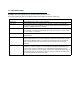
Identify the connectors and switches on the back panel and attach the necessary Netopia Router cables.
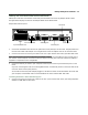
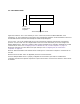
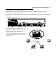
The figure below displays the back of the Netopia R6000 Series ADSL Router.
Netopia R6000 Series back panel
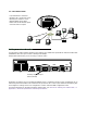
1. Connect the mini-DIN8 connector from the power brick to the power port on the router. Plug the power brick
into the brick-to-wall outlet adapter cord. Plug the other end of the adapter cord into an electrical outlet.
2. Connect one end of one of the RJ-45 cables to the Line 1 port and the other end to your ADSL wall outlet.
Note: You may need to use the included DSL line adapter in order to accommodate the type of phone lines in
your location. Some telephone connections have the copper line cable pairs reversed, and the line adapter is
supplied to compensate for this configuration.
3. Connect the other RJ-45 cable to your computer’s Ethernet port and to any of the Ethernet ports on the
router.
(If you are connecting the router to an existing Ethernet hub, use Ethernet port #1 on the router and set the
crossover switch to the Uplink position.)
You should now have the power adapter plugged in, the Ethernet cable connected between the router and
your computer, and the ADSL cable connected between the router and the ADSL wall outlet.
Connecting the R6120 or R6131 Dial Backup ports
4. Connect one end of one of the RJ-45 cables to the Line 2 port and the other end to your analog telephone
(R6120) or ISDN (R6131) wall outlet.
Ethernet
Normal
Auxiliary Console Power
Line 1
8 port Ethernet hub
Crossover switch
Line ports
Auxiliary port
Console port
Power port
8
1
1
Uplink
Line 2