® Netopia 3366C-ENT ADSL Router with V.
Copyright ©2004 Netopia, Inc., v.032504 Netopia and the Netopia logo are registered trademarks belonging to Netopia, Inc., registered U.S. Patent and Trademark Office. Broadband Without Boundaries is a trademark belonging to Netopia, Inc. All other trademarks are the property of their respective owners. All rights reserved. Netopia, Inc. 6001 Shellmound Street, 4th Floor Emeryville, CA 94608 U.S.A.
Contents Contents 3 Chapter 1 — Introduction..........................................................1-1 Overview ....................................................................... 1-1 Features and Capabilities ............................................... 1-1 How to Use this Guide.................................................... 1-2 Chapter 2 — Making the Physical Connections..........................2-1 Find a Location ..............................................................
Getting Started Guide 3. IP Easy Setup .................................................. 6-6 4. Easy Setup Security Configuration ..................... 6-7 Chapter 7 — Line Backup .........................................................7-1 Configuring Backup ........................................................ 7-1 Connection Profiles ........................................................ 7-2 IP Setup .............................................................. 7-7 WAN Configuration ...........
Introduction 1-1 Chapter 1 Introduction Overview The Netopia 3366C-ENT ADSL Router with V.92 Backup is a full-featured ADSL router for connecting diverse local area networks (LANs) to the Internet and other remote networks. The Netopia 3366C-ENT ADSL Router with V.92 Backup connects easily to your DSL line to provide your whole network with a high-speed connection to the outside world. In addition, the V.
1-2 Getting Started Guide • Built-in firewall protects LAN resources from Internet intruders • Backup Default Gateway feature with an external router enables high-availability solutions • Menu-driven or CLI interfaces via Telnet or serial Console • Easy Setup with menu-driven interface • Tiered Access, 2 levels of configuration access • Configuration Management, up to 3 backup configurations • TFTP download/upload of new firmware and configuration files • System diagnostics and logs • SNMP
Making the Physical Connections 2-1 Chapter 2 Making the Physical Connections This section tells you how to make the physical connections to your Netopia 3366C-ENT ADSL Router with V.92 Backup. This section covers the following topics: • “Find a Location” on page 2-1 • “What You Need” on page 2-1 • “Important Safety Instructions” on page 2-2 • “Identify the Connectors and Attach the Cables” on page 2-3 • “Netopia 3366C-ENT ADSL Router with V.
2-2 Getting Started Guide You will need: • A Windows–based PC or a Macintosh computer with Ethernet connectivity for configuring the Netopia 3366C-ENT. This may be built-in Ethernet or an add-on card, with TCP/IP installed and configured. See “Configuring TCP/IP” on page 4-1. • A phone jack to which your ADSL provider is providing ADSL service. (Your phones and ADSL service generally use the same phone line.
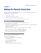
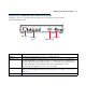
Making the Physical Connections 2-3 Identify the Connectors and Attach the Cables Identify the connectors on the back panel and attach the necessary Netopia Router cables. Netopia 3366C-ENT back panel DSL 4 3 LAN 2 DSL port Ethernet ports 1 Console Power Off / On Power port Console port . Port Description DSL port Ethernet ports An RJ-11 jack labeled DSL to connect to your ADSL wall jack. Four RJ-45 10/100Base-T Ethernet jacks. You can use one of these to configure the Netopia 3366C-ENT.
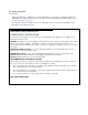
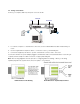
2-4 Getting Started Guide Connect your computer, DSL line, and power source as shown. Ethernet DSL DC Power DSL 4 2 3 LAN 2 1 Console 1 Power Off / On 3 1. For a direct computer to router Ethernet connection, use the standard Ethernet cable included with your router. 2. Use the supplied RJ-11 telephone cable to connect the router to your DSL wall jack. 3. Connect the supplied power brick to a power outlet and the connector end to the router.
Making the Physical Connections 2-5 Netopia 3366C-ENT ADSL Router with V.92 Backup Status Lights The figure below represents the Netopia 3366C-ENT status light (LED) panel. 2 nc Sy L DS LA 3 N LA 4 N LA p N lU LA Dia N 1 Netopia 3366C-ENT status indicator lights Power: Solid green when the power is on Flashes red for firmware upgrade DSL Sync Solid green when connected Flashes green for traffic on the WAN LAN 1, 2, 3, 4 Solid green when connected to each port on the LAN.
2-6 Getting Started Guide
Connecting to Your Local Area Network 3-1 Chapter 3 Connecting to Your Local Area Network This chapter describes how to physically connect the Netopia 3366-ENT to your local area network (LAN). Before you proceed, make sure the Netopia 3366-ENT is properly configured. You can customize the router’s configuration for your particular LAN requirements using console-based management (see “Console-Based Management” on page 5-1).
3-2 Getting Started Guide Ethernet: Ethernet hardware and software drivers enable your PC or Macintosh computer to communicate on the LAN. Once the Netopia 3366-ENT is properly configured and connected to your LAN, PC and Macintosh computers that have their required components in place will be able to connect to the Internet or other remote IP networks. Connecting to an Ethernet Network You can connect a standard 10/100Base-T Ethernet network to the Netopia 3366-ENT using any of its Ethernet ports.
Connecting to Your Local Area Network 3-3 If you add devices connected through a hub or switch, connect the hub or switch to an Ethernet port on the Netopia 3366-ENT. The Netopia 3366-ENT in a 10/100Base-T network To connect your 10/100Base-T network to the Netopia 3366-ENT through an Ethernet port, use standard Category 5 Ethernet cables with RJ-45 connectors. DSL 4 You can attach additional devices using standard Category 5 Ethernet cables (not provided).
3-4 Getting Started Guide
Configuring TCP/IP 4-1 Chapter 4 Configuring TCP/IP Once you have set up your physical local area network, you will need to configure Internet Protocol (TCP/IP) on each client workstation connected to your Netopia 3366C-ENT. This chapter describes how to configure TCP/IP for both Windows-based and Macintosh computers.
4-2 Getting Started Guide b. Some Windows versions follow a path like this: Start menu -> Control Panel -> Network and Internet Connections -> Network Connections -> Local Area Connection -> Properties -> Internet Protocol [TCP/IP] -> Properties Then go to Step 2. Step 2. Select Obtain an IP address automatically. Step 3. Select Obtain DNS server address automatically, if available. Step 4. Remove any previously configured Gateways, if available. Step 5. OK the settings. Restart if prompted.
Configuring TCP/IP 4-3 Configuring TCP/IP on Macintosh Computers The following is a quick guide to configuring TCP/IP for MacOS computers. Configuring TCP/IP in a Macintosh computer requires the following: • You must have Open Transport installed, standard in MacOS 8 and higher and optional in earlier system versions. • You must have built-in Ethernet or a third-party Ethernet card and its associated drivers installed in your Macintosh. Macintosh MacOS 8 or higher or Mac OS X Step 1.
4-4 Getting Started Guide Step 3. Select Configure Using DHCP Step 4. Close and Save, if prompted. NOTE: You can use these instructions to configure other computers on your network to accept IP addresses served by the Netopia 3366C-ENT.
Console-Based Management 5-1 Chapter 5 Console-Based Management Console-based management is a menu-driven interface for the capabilities built into the Netopia 3366C-ENT. Console-based management provides access to a wide variety of features that the router supports. You can customize these features for your individual setup. This chapter describes how to access the Console-based management screens.
5-2 Getting Started Guide reconfiguring the manner in which you may be using the router to connect to more than one service provider or remote site.
Console-Based Management 5-3 • If you connect a PC with Microsoft Windows, you can use a Windows Telnet application or simply run Telnet from the Start menu. • If you connect a Macintosh computer running Classic Mac OS, you can use the NCSA Telnet program supplied on the Netopia CD. You install NCSA Telnet by dragging the application from the CD to your hard disk. Mac OS X users can use the Terminal application that comes with Mac OS X in the Utilities folder.
5-4 Getting Started Guide Launch your terminal emulation software and configure the communications software for the values shown in the table below. These are the default communication parameters that the Netopia 3366C-ENT uses. Parameter Suggested Value Terminal type PC: ANSI-BBS Mac: ANSI, VT-100, or VT-200 Data bits 8 Parity None Stop bits 1 Speed Options are: 9600, 19200, or 38400 bits per second Flow Control None Note: The router firmware contains an autobaud detection feature.
Easy Setup 6-1 Chapter 6 Easy Setup This chapter describes how to use the Easy Setup Console screens on your Netopia 3366C-ENT. After completing the Easy Setup Console screens, your router will be ready to connect to the Internet or another remote site.
6-2 Getting Started Guide Quick Easy Setup Connection Path This section may be all you need to do to configure your Netopia 3366C-ENT ADSL Router with V.92 Backup. Your service provider will supply you with several parameter values.
Easy Setup 6-3 The following steps will get you up and running quickly: 1. Open a Telnet session to 192.168.1.1 to bring up the Main Menu. If you don't know how to do this, see “Connecting through a Telnet Session” on page 5-2. The Main Menu appears. Netopia 3366C-ENT Easy Setup... WAN Configuration... System Configuration... Utilities & Diagnostics... Statistics & Logs... Quick Menus... Quick View...
6-4 Getting Started Guide 1. ADSL Line Configuration ADSL Line Configuration Trellis Coding Enabled: On Fast Retrain Enabled: On Wiring Type... Data Link Encapsulation... AutoSense RFC1483 Data Circuit VPI (0-255): Data Circuit VCI (32-65535): 8 35 PREVIOUS SCREEN NEXT SCREEN Return/Enter brings you to next screen. 1. Select Trellis Coding Enabled. Toggle it to On (the default) or Off. Unless otherwise specified by your provider, you can accept this default. 2. Select Fast Retrain Enabled.
Easy Setup 6-5 2. Easy Setup Profile The Easy Setup Profile screen is where you configure the parameters that control the Netopia 3366C-ENT’s connection to a specific remote destination, usually your ISP or a corporate site. On a Netopia 3366C-ENT you can add up to 15 more connection profiles, for a total of 16, although you can only use one at a time, unless you are using Virtual Private Networks (VPNs). Connection Profile 1: Easy Setup Profile Underlying Encapsulation... RFC1483 Mode...
6-6 Getting Started Guide 3. IP Easy Setup The IP Easy Setup screen is where you enter information about your Netopia Router’s: • Ethernet IP address • Ethernet Subnet mask • Domain Name • Domain Name Server IP address • Default gateway IP address Consult with your network administrator to obtain the information you will need. For more information about setting up IP, see the Firmware User’s Guide chapter on “IP Setup”. IP Easy Setup Ethernet IP Address: Ethernet Subnet Mask: 192.168.1.1 255.
Easy Setup 6-7 5. Type the Primary Domain Name Server address your ISP gave you. Press Return. A new field Secondary Domain Name Server will appear. If your ISP gave you a secondary domain name server address, enter it here. Press Return until the next field Default IP Gateway is highlighted. 6. If you do not enter a Default IP Gateway value, the router defaults to the remote IP address you entered in the Easy Setup connection profile.
6-8 Getting Started Guide Easy Setup Security Configuration It is strongly suggested that you password-protect configuration access to your Netopia. By entering a Name and Password pair here, access via serial, Telnet, and SNMP will be password-protected. Be sure to remember what you have typed here, because you will be prompted for it each time you configure this Netopia.
Line Backup 7-1 Chapter 7 Line Backup The Netopia 3366C-ENT offers line backup functionality in the event of a line failure on the DSL primary WAN link: • to its internal V.92 modem or • to a backup default gateway.
7-2 Getting Started Guide Detailed descriptions follow. Connection Profiles The dial backup feature allows you to configure a complete Connection Profile for the modem backup, just as you do for your primary WAN connection. In this way profiles are associated with a particular interface. It should have switched characteristics for modem backup. Navigate to the Add Connection Profile screen.
Line Backup 7-3 Add Connection Profile Profile Name: Profile Enabled: Encapsulation Type... Encapsulation Options... IP Profile Parameters... COMMIT Profile 1 +-------------+ +-------------+ | PPP | | RFC1483 | | ATMP | | PPTP | | IPsec | | L2TP | +-------------+ CANCEL Assuming you selected PPP, new fields appear. Add Connection Profile Profile Name: Profile Enabled: Modem Backup Yes Encapsulation Type... PPP Encapsulation Options... IP Profile Parameters... Interface Group... Telco Options...
7-4 Getting Started Guide The Datalink (PPP/MP) Options screen appears. Datalink (PPP/MP) Options Data Compression... +------+rd LZS +------+ | None | | PAP | | CHAP | +------+ Send Authentication... Send User Name: Send Password: Receive User Name: Receive Password: Dial on Demand: PAP-- Yes Password protection is used. Passwords are exchanged in clear text. • Data Compression should remain set to Standard LZS.
Line Backup 7-5 • Select IP Profile Parameters. The IP Profile Parameters screen appears. IP Profile Parameters Address Translation Enabled: IP Addressing... NAT Map List... NAT Server List... NAT Options... Stateful Inspection Enabled: Yes Unnumbered Easy-PAT List Easy-Servers Local WAN IP Address: 0.0.0.0 Remote Remote Filter Remove 0.0.0.0 0.0.0.0 IP Address: IP Mask: Set... Filter Set No RIP Profile Options... Toggle to Yes if this is a single IP address ISP account.
7-6 Getting Started Guide Telco Options Dial... Dial In/Out Dialing Prefix: Number to Dial: Alternate Site to Dial: Dial on Demand: Idle Timeout (seconds): Yes 300 Callback: No CompuServe Login Enabled: No • From the Dial pop-up menu, you can choose whether to Dial Out Only, Dial In Only, or Dial In/Out (default). • Dialing Prefix: If you are connected to a Centrex or PBX phone system that requires you to dial a prefix number (such as “9” for an outside line), enter it here.
Line Backup 7-7 IP Setup Here, you set the IP address of the alternate gateway. Navigate to the IP Setup screen under the System Configuration menu. Main Menu IP Setup System Configuration IP Setup Ethernet IP Address: Ethernet Subnet Mask: Define Additional Subnets... 192.168.1.1 255.255.255.0 Default IP Gateway: Backup IP Gateway: Primary Domain Name Server: Secondary Domain Name Server: Domain Name: 0.0.0.0 0.0.0.0 0.0.0.0 0.0.0.0 Rip Options... Multicast Forwarding... Static Routes...
7-8 Getting Started Guide WAN Configuration To configure the modem characteristics, from the Main Menu select WAN Configuration and then WAN Setup. Main Menu WAN Configuration WAN Setup WAN Configuration WAN (Wide Area Network) Setup... ATM Circuits Configuration... Display/Change Connection Profile... Add Connection Profile... Delete Connection Profile... WAN Default Profile... ATMP/PPTP Default Profile... IKE Phase 1 Configuration... Advanced Connection Options...
Line Backup 7-9 Choose the interface to configure for backup, MODEM (Wan Module 2) Setup. The Internal Modem Setup screen appears. Internal Modem Setup Modem Dialing Prefix: PBX Dialing Prefix: Line Directory Number: Speaker On... Speaker Volume... Answer Incoming calls... Country... ATDT Until Carrier 2-Medium Always United States Enter the dialing prefix to be sent to all modems. • Modem Dialing Prefix: ATDT is the standard Hayes-compatible code for alerting the modem itself.
7-10 Getting Started Guide Backup Configuration screen Navigate to the Backup Configuration screen. Main Menu WAN Configuration Advanced Connection Options Backup Configuration This screen is used to configure the conditions under which backup will occur, if it will recover, and how the modem is configured. For the internal V.
Line Backup 7-11 Note: If you want the router to initiate the backup connection on loss of Layer 1 or 2 only (Physical or Data link Layer), leave Ping Host Name or IP Address blank. Do not use 0.0.0.0 in this field. Hit the space bar or Delete key to CLEAR the field totally. Leaving 0.0.0.0 in this field tells the router to ping an address that does not exist. • Select Recovery to ADSL and press Return.
7-12 Getting Started Guide Using Scheduled Connections with Backup The backup link is a PPP dial-up connection and only connects to the Internet service provider when traffic is initiated from the LAN. If you want to use the backup link to provide redundancy for services, such as a Web service that you provide to the outside world, you must force the connection to stay up. You do this by creating a scheduled connection entry that will be a permanent “forced up” connection for the backup modem.
Line Backup 7-13 Add Scheduled Connection Scheduled Connection Enable: On How Often... Weekly Schedule Type... Forced Up Set Weekly Schedule... Use Connection Profile... ADD SCHEDULED CONNECTION CANCEL Return/Enter accepts * Tab toggles * ESC cancels. Scheduled Connections dial remote Networks on a Weekly or Once-Only basis. • Toggle Scheduled Connection Enable to On. • From the How Often pop-up menu, select Weekly and press Return.
7-14 Getting Started Guide • Select Use Connection Profile, and press Return. A screen displays all of your Connection Profiles. Select the one you want to apply this scheduled connection to and press Return. Your selection becomes effective. Now, if your primary WAN link fails, the backup link will become active and remain active until the primary link recovers. For more information about Scheduled Connections, see the Firmware User’s Guide.
Line Backup 7-15 • the IP Setup screen in the System Configuration menu Here, you set the IP address of the alternate gateway device. IP Setup Ethernet IP Address: Ethernet Subnet Mask: Define Additional Subnets... 192.168.1.1 255.255.255.0 Default IP Gateway: Backup IP Gateway: Primary Domain Name Server: Secondary Domain Name Server: Domain Name: 0.0.0.0 0.0.0.0 0.0.0.0 0.0.0.0 Rip Options... Multicast Forwarding... Static Routes... None IP Address Serving...
7-16 Getting Started Guide
Technical Specifications and Safety Information 8-1 Chapter 8 Technical Specifications and Safety Information Description Dimensions: 7.5” (19.5 cm) (w) x 6.75” (17 cm) (d) x 1.5" (3.5 cm) (h) Communications interfaces: The Netopia 3366C-ENT ADSL Router with V.92 Backup has an RJ-11 jack for WAN line connections, a 4–port 10/100Base-T Ethernet switch for your LAN connections, and a DB-9 Console port for alternative access to the configuration menus. Power requirements • 12 VDC input • 1.
8-2 Getting Started Guide Agency approvals North America Safety Approvals: • United States – UL 60950 Third Edition • Canada – CSA: CAN/CSA-C22.2 No. 60950-00 EMC: • United States – FCC Part 15 Class B • Canada – ICES-003 Telecom: • United States – FCC Part 68 • Canada – CS-03 International Safety Approvals: • Low Voltage (European directive) 73/23 • EN60950 (Europe) EMI Compatibility: • 89/336/EEC (European directive) • EN55022:1994 • EN300 386 V1.2.
Technical Specifications and Safety Information 8-3 Manufacturer’s Declaration of Conformance Note: Warnings: This is a Class B product. In a domestic environment this product may cause radio interference, in which case the user may be required to take adequate measures. Adequate measures include increasing the physical distance between this product and other electrical devices.
8-4 Getting Started Guide Repairs to the certified equipment should be made by an authorized Canadian maintenance facility designated by the supplier. Any repairs or alterations made by the user to this equipment, or equipment malfunctions, may give the telecommunications company cause to request the user to disconnect the equipment.
Technical Specifications and Safety Information 8-5 • Do not use the telephone to report a gas leak in the vicinity of the leak. FCC Part 68 Information a) This equipment complies with Part 68 of the FCC rules and the requirements adopted by the ACTA. On the bottom of this equipment is a label that contains, among other information, a product identifier in the format US:AAAEQ##TXXXX. If requested, this number must be provided to the telephone company.
8-6 Getting Started Guide RF Exposure Statement: Note: NOTE: Installation of the wireless models must maintain at least 20 cm between the wireless router and any body part of the user to be in compliance with FCC RF exposure guidelines. Electrical Safety Advisory Telephone companies report that electrical surges, typically lightning transients, are very destructive to customer terminal equipment connected to AC power sources. This has been identified as a major nationwide problem.