® Netopia 3347W/3357W-ENT ADSL Wireless Router Getting Started Guide
Copyright ©2003 Netopia, Inc., v.081203 All rights reserved. Printed in the U.S.A. This manual and any associated artwork, software, and product designs are copyrighted with all rights reserved. Under the copyright laws such materials may not be copied, in whole or part, without the prior written consent of Netopia, Inc. Under the law, copying includes translation to another language or format. Netopia, Cayman, and “Making Broadband Work” are registered trademarks of Netopia, Inc. All rights reserved.
Contents Contents 3 Chapter 1 — Introduction..........................................................1-5 Overview ....................................................................... 1-5 Features and Capabilities ............................................... 1-5 How to Use this Guide.................................................... 1-6 Chapter 2 — Making the Physical Connections..........................2-1 Find a Location ..............................................................
Getting Started Guide 4. Easy Setup Security Configuration ..................... 6-8 Chapter 7 — Wireless LAN Configuration ...................................7-1 Wireless Configuration ................................................... 7-1 Appendix A — Technical Specifications and Safety Information ..A-1 Description.................................................................... A-1 Power requirements ............................................. A-1 Environment ..................................
Introduction 1-5 Chapter 1 Introduction Overview The Netopia 3347W/3357W-ENT ADSL Wireless Router is a full-featured, ADSL router for connecting both wired and wireless local area networks (LANs) to the Internet and other remote networks. The Netopia 3347W/3357W-ENT ADSL Wireless Router connects easily to your ADSL service to provide your whole network with a high-speed connection to the outside world.
1-6 Getting Started Guide • IPSec implementation supports DES or 3DES encryption, MD5 or SHA1 encapsulation, and manual or IKE keying • Built-in stateful firewall and packet-filtering firewall features protect LAN resources from Internet intruders • Backup Default Gateway feature with an external router enables high-availability solutions • Menu-driven or CLI interfaces via Telnet • Easy Setup with menu-driven interface • Tiered Access, 2 levels of configuration access • Configuration Managemen
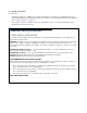
Making the Physical Connections 2-1 Chapter 2 Making the Physical Connections This section tells you how to make the physical connections to your Netopia 3347W/3357W-ENT ADSL Wireless Router.
2-2 Getting Started Guide You will need: • A Windows–based PC or a Macintosh computer with Ethernet connectivity for configuring the Netopia 3347W/3357W-ENT. This may be built-in Ethernet or an add-on card, with TCP/IP installed and configured. See “Configuring TCP/IP” on page 4-5. • A phone jack to which your ADSL provider is providing ADSL service. (Your phones and ADSL service generally use the same phone line.
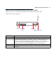
Making the Physical Connections 2-3 Identify the Connectors and Attach the Cables Identify the connectors on the back panel and attach the necessary Netopia Router cables. Netopia 3347W/3357W-ENT back panel DSL 4 3 LAN 2 DSL port Ethernet ports 1 Power Off / On Power port Wireless antenna . Port DSL port Ethernet ports Power port Wireless antenna Description An RJ-11 jack labeled DSL to connect to your DSL wall outlet. Four RJ-45 10/100Base-T Ethernet jacks.
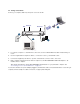
2-4 Getting Started Guide Connect your computer, DSL line, and power source as shown. Ethernet DSL 4 DC Power DSL 4 3 LAN 2 1 Power Off / On 2 1 3 1. For a direct computer to router Ethernet connection, use the standard Ethernet cable included with your router. 2. Use the supplied RJ-11 telephone cable to connect the router to your DSL wall outlet. 3. Connect the supplied power brick to a power outlet and the connector end to the router. 4.
Making the Physical Connections 2-5 Netopia 3347W/3357W-ENT ADSL Wireless Router Status Lights The figure below represents the Netopia 3347W/3357W-ENT status light (LED) panel. Netopia 3347W/3357W-ENT status indicator lights Power: Solid green when the power is on DSL Sync Flashes green when training Solid green when trained Flashes green for DSL traffic LAN 1, 2, 3, 4 Solid green when connected to each port on the LAN. Flash green when there is activity on each port.
2-6 Getting Started Guide
Connecting to Your Local Area Network 3-1 Chapter 3 Connecting to Your Local Area Network This chapter describes how to physically connect the Netopia 3347W/3357W-ENT to your local area network (LAN). Before you proceed, make sure the Netopia 3347W/3357W-ENT is properly configured. You can customize the router’s configuration for your particular LAN requirements using console-based management (see “Telnet-Based Management” on page 5-1).
3-2 Getting Started Guide Ethernet: Ethernet hardware and software drivers enable your PC or Macintosh computer to communicate on the LAN. Once the Netopia 3347W/3357W-ENT is properly configured and connected to your LAN, PC and Macintosh computers that have their required components in place will be able to connect to the Internet or other remote IP networks.
Connecting to Your Local Area Network 3-3 If you add devices connected through a hub or switch, connect the hub or switch to an Ethernet port on the Netopia 3347W/3357W-ENT. The Netopia 3347W/3357W-ENT in a 10/100Base-T network To connect your 10/100Base-T network to the Netopia 3347W/3357W-ENT through the Ethernet port, use standard Category 5 Ethernet cables with RJ-45 connectors.
3-4 Getting Started Guide The Netopia 3347W/3357W-ENT in an 802.11b wireless network To create your 802.11b wireless network you must install a Wi-Fi CERTIFIED™ wireless adapter card in each computer that will join the wireless LAN. Many manufacturers offer such adapter cards for almost all major brands of computers. You can find lists of these adapters on the Wi-Fi Alliance website: http://www.weca.net.
Configuring TCP/IP 4-5 Chapter 4 Configuring TCP/IP Once you have set up your physical local area network, you will need to configure Internet Protocol (TCP/IP) on each client workstation connected to your Netopia 3347W/3357W-ENT. This chapter describes how to configure TCP/IP for both Windows-based and Macintosh computers.
4-6 Getting Started Guide b. Some Windows versions follow a path like this: Start menu -> Control Panel -> Network and Internet Connections -> Network Connections -> Local Area Connection -> Properties -> Internet Protocol [TCP/IP] -> Properties Then go to Step 2. Step 2. Select Obtain an IP address automatically. Step 3. Select Obtain DNS server address automatically, if available. Step 4. Remove any previously configured Gateways, if available. Step 5. OK the settings. Restart if prompted.
Configuring TCP/IP 4-7 Configuring TCP/IP on Macintosh Computers Configuring TCP/IP in a Macintosh computer requires the following: • You must have Open Transport installed, standard in MacOS 8 and higher and optional in earlier system versions. • You must have built-in Ethernet or a third-party Ethernet card and its associated drivers installed in your Macintosh. Macintosh MacOS 8 or higher or Mac OS X Step 1. Access the TCP/IP or Network control panel. a.
4-8 Getting Started Guide Step 3. Select Configure Using DHCP Step 4. Close and Save, if prompted. NOTE: You can use these instructions to configure other computers on your network to accept IP addresses served by the Netopia 3347W/3357W-ENT.
Telnet-Based Management 5-1 Chapter 5 Telnet-Based Management Telnet-based management is a menu-driven interface for the capabilities built into the Netopia 3347W/3357W-ENT. Telnet-based management provides access to a wide variety of features that the router supports. You can customize these features for your individual setup. This chapter describes how to access the Telnet-based management screens.
5-2 Getting Started Guide • The System Configuration menus display and permit changing: • IP Setup • Filter Sets • IP Address Serving • Network Address Translation (NAT) • Date and Time • SNMP (Simple Network Management Protocol) • Security • Upgrade Feature Set • Change Device to a Bridge • Logging • The Utilities & Diagnostics menus provide a selection of seven tools for monitoring and diagnosing the router's behavior, as well as for updating the firmware and rebooting the system.
Telnet-Based Management 5-3 • If you connect a PC with Microsoft Windows, you can use a Windows Telnet application or simply run Telnet from the Start menu. • If you connect a Macintosh computer running Classic Mac OS, you can use the NCSA Telnet program supplied on the Netopia CD. You install NCSA Telnet by dragging the application from the CD to your hard disk. Mac OS X users can use the Terminal application that comes with Mac OS X in the Utilities folder.
5-4 Getting Started Guide
Easy Setup 6-1 Chapter 6 Easy Setup This chapter describes how to use the Easy Setup Telnet screens on your Netopia 3347W/3357W-ENT. After completing the Easy Setup Telnet screens, your router will be ready to connect to the Internet or another remote site.
6-2 Getting Started Guide Quick Easy Setup Connection Path This section may be all you need to configure your Netopia 3347W/3357W-ENT ADSL Wireless Router. Your service provider will supply you with several parameter values.
Easy Setup 6-3 The following steps will get you up and running quickly: 1. Open a Telnet session to 192.168.1.1 to bring up the Main Menu. If you don't know how to do this, see “Connecting through a Telnet Session” on page 5-2. The Main Menu appears. Netopia 3347W/3357W-ENT Easy Setup... WAN Configuration... System Configuration... Utilities & Diagnostics... Statistics & Logs... Quick Menus... Quick View...
6-4 Getting Started Guide 1. DSL Line Configuration ADSL Line Configuration Trellis Coding Enabled: On Fast Retrain Enabled: On Wiring Type... Data Link Encapsulation... RFC1483 Mode... PPP over Ethernet (PPPoE): Tip/Ring (Inner Pair) RFC1483 Bridged 1483 Off Data Circuit VPI (0-255): Data Circuit VCI (32-65535): 8 35 PREVIOUS SCREEN NEXT SCREEN 1. Select Trellis Coding Enabled. Toggle it to On (the default) or Off. Unless otherwise specified by your provider, you can accept this default. 2.
Easy Setup 6-5 2. Easy Setup Profile The Easy Setup Profile screen is where you configure the parameters that control the Netopia 3347W/3357W-ENT’s connection to a specific remote destination, usually your ISP or a corporate site. On a Netopia 3347W/3357W-ENT you can add up to 15 more connection profiles, for a total of 16, although you can only use one at a time, unless you are using Virtual Private Networks (VPNs).
6-6 Getting Started Guide 3. If you selected PPP data link encapsulation in the DSL Line Configuration screen, a PPP Authentication menu item appears. The authentication protocol and user name/password combinations you enter must be assigned or agreed to in advance between you and your ISP. Select PPP Authentication and press Return.
Easy Setup 6-7 Because this is a private network address, it should never be directly connected to the Internet. Using NAT for all your connection profiles will ensure this restriction. See the Firmware User’s Guide chapter on “Multiple Network Address Translation (MultiNAT)” for more information. 2. Select Ethernet Subnet Mask and enter the subnet mask your ISP has given you only if you are not using NAT.
6-8 Getting Started Guide 4. Easy Setup Security Configuration The Easy Setup Security Configuration screen lets you password-protect your Netopia 3347W/3357W-ENT. Input your Write Access Name and Write Access Password with names or numbers totaling up to eleven digits. If you password protect the Telnet screens, you will be prompted to enter the name and password you have specified every time you log in to the Telnet screens. Do not forget your name and password.
Wireless LAN Configuration 7-1 Chapter 7 Wireless LAN Configuration This chapter describes how to use the Telnet-based management screens to access and configure advanced features of your equipment’s wireless networking and security. Wireless Configuration To access the system configuration screens, select System Configuration in the Main Menu, then press Return. The System Configuration menu screen appears: System Configuration IP Setup... Filter Sets... IP Address Serving...
7-2 Getting Started Guide Wireless LAN Configuration Enable Wireless: Yes SSID: Channel... Closed System... Enable WEP... 4405 2605 6 Open Off Return/Enter accepts * Tab toggles * ESC cancels. Enable Wireless is set to Yes by default. When Enable Wireless is disabled (No), the Gateway will not provide or broadcast any wireless LAN services. • SSID (Wireless ID): The SSID is preset to a number that is unique to your unit.
Wireless LAN Configuration 7-3 Wireless LAN Configuration Key Key Key Key Enable Wireless: Yes SSID: Channel... Closed System... Enable WEP... 4405 2605 6 Open On - Manual Default Key... 1 1 (40b): 9a82ff3d92 2 (128b): 2f5d42db7b734ff4e17b65881e 3 (128b): db298860b6f380e6daec7dbfd4 4 (40b): c8e5281016 Enter 10 digits for 40 bit, 26 digits for 128 bit, or 58 for 256bit WEP. You can then configure: • Channel: (1 through 11) on which the network will broadcast.
7-4 Getting Started Guide The pull-down menu for enabling WEP offers three settings: Off, On - Automatic, and On - Manual. You are strongly encouraged to enable WEP encryption on your wireless LAN. • Off provides no encryption on your wireless LAN data. Wireless LAN Configuration Enable Wireless: Yes SSID: Channel... Closed System... Enable WEP... 4405 2605 6 Open On - Automatic Default Key...
Wireless LAN Configuration 7-5 • On - Manual allows you to enter your own encryption keys manually. This is a difficult process, but only needs to be done once. Avoid the temptation to enter all the same characters. Wireless LAN Configuration Key Key Key Key Enable Wireless: Yes SSID: Channel... Closed System... Enable WEP... 4405 2605 6 Open On - Manual Default Key...
7-6 Getting Started Guide Utilities & Diagnostics... Ping... Trace Route... Telnet... Disconnect Telnet Console Session... Trivial File Transfer Protocol (TFTP)... Restart System... Revert to Factory Defaults... Select Restart System and press Return. You will be prompted to confirm this choice. Select CONTINUE and press Return. Utilities & Diagnostics...
Technical Specifications and Safety Information A-1 Appendix A Technical Specifications and Safety Information Description Dimensions: 5.25” (13.5 cm) (w) x 5.25" (13.5 cm) (d) x 1.5" (3.5 cm) (h) Communications interfaces: The Netopia 3347W/3357W-ENT ADSL Wireless Router has an RJ-11 jack for DSL line connections and a 4–port 10/100Base-T Ethernet switch for your LAN connections. The Netopia 3347W/3357W-ENT contains an 802.11b wireless LAN transmitter. Power requirements • 12 VDC input • 1.
A-2 Getting Started Guide Agency approvals North America Safety Approvals: • United States – UL 60950, Third Edition • Canada – CSA: CAN/CSA-C22.2 No.
Technical Specifications and Safety Information A-3 Manufacturer’s Declaration of Conformance Note: Warnings: This is a Class B product. In a domestic environment this product may cause radio interference, in which case the user may be required to take adequate measures. Adequate measures include increasing the physical distance between this product and other electrical devices.
A-4 Getting Started Guide Before installing this equipment, users should ensure that it is permissible to be connected to the facilities of the local telecommunications company. The equipment must also be installed using an acceptable method of connection. In some cases, the company’s inside wiring associated with a single line individual service may be extended by means of a certified connector assembly (telephone extension cord).
Technical Specifications and Safety Information A-5 • Never touch uninsulated telephone wires or terminals unless the telephone line has been disconnected at the network interface. • Use caution when installing or modifying telephone lines. • Avoid using a telephone (other than a cordless type) during an electrical storm. There may be a remote risk of electric shock from lightning. • Do not use the telephone to report a gas leak in the vicinity of the leak.
A-6 Getting Started Guide d) The REN is used to determine the number of devices that may be connected to a telephone line. Excessive RENs on a telephone line may result in the devices not ringing in response to an incoming call. In most but not all areas, the sum of RENs should not exceed five (5.0). To be certain of the number of devices that may be connected to a line, as determined by the total RENs, contact the local telephone company.