
Data Sheet

Features highlights
Switching Features
VLAN Support • VLANs are collections of switching ports that comprise a single broadcast domain. Packets are classified
as belonging to a VLAN based on either the VLAN tag or a combination of the ingress port and packet
contents. Packets sharing common attributes can be groups in the same VLAN. The switch soware is in
full compliance with IEEE 802.1Q VLAN tagging.
Double VLAN • The Double VLAN feature (IEEE 802.1QinQ) allows the use of a second tag on network trac. The
additional tag helps dierentiate between customers in the Metropolitan Area Networks (MAN) while
preserving individual customer’s VLAN identification when they enter their own 802.1Q domain.
Switching Modes • The switchport mode feature helps to minimize the potential for configuration errors. The feature also
makes VLAN configuration easier by reducing the amount of commands needed for port configuration. For
example, to configure a port connected to an end user, you can configure the port in Access mode. Ports
connected to other switches can be configured in Trunk mode. VLAN assignments and tagging behavior are
automatically configured as appropriate for the connection type.
Spanning Tree Protocols (STP) • Spanning Tree Protocol (IEEE 802.1D) is a standard requirement of Layer 2 switches that allows bridges
to automatically prevent and resolve L2 forwarding loops. The STP feature supports a variety of per-port
settings including path cost, priority settings, Port Fast mode, STP Root Guard, Loop Guard, TCN Guard,
and Auto Edge. These settings are also configurable per-Port-channel.
Rapid Spanning Tree • Rapid Spanning Tree Protocol (RSTP) detects and uses network topologies to enable faster spanning tree
convergence aer a topology change, without creating forwarding loops. The port settings supported by
STP are also supported by RSTP.
Multiple Spanning Tree • Multiple Spanning Tree (MSTP) operation maps VLANs to spanning tree instances. Packets assigned
to various VLANs are transmitted along dierent paths within MSTP Regions (MST Regions). Regions
are one or more interconnected MSTP bridges with identical MSTP settings. The MSTP standard lets
administrators assign VLAN trac to unique paths.
• M4500 supports IEEE 802.1Q-2005, which is a version of corrected problems associated with the
previous version. It provides for faster transition-to-forwarding, and incorporates new features for a port
(restricted role and restricted TCN).
Bridge Protocol Data Unit (BPDU) Guard • Spanning Tree BPDU Guard is used to disable the port in case a new device tries to enter the already
existing topology of STP. Thus devices, which were originally not a part of STP, are not allowed to influence
the STP topology.
Port-channel • Up to 32 ports can combine to form a single Port-Channel (LAG). This enables fault tolerance protection
from physical link disruption, higher bandwidth connections and improved bandwidth granularity. A Port-
channel is composed of ports of the same speed, set to full-duplex operation
Link Aggregate Control Protocol (LACP) • Link Aggregate Control Protocol (LACP) uses peer exchanges across links to determine, on an ongoing
basis, the aggregation capability of various links, and continuously provides the maximum level of
aggregation capability achievable between a given pair of systems. LACP automatically determines,
configures, binds, and monitors the binding of ports to aggregators within the system.
Multi Chassis Link Aggregation Group (MLAG) • This feature enables a Port-channel to be created across two independent units, which creates a scenario
where some member ports of the MLAG can reside on one unit and the other members of the MLAG
can reside on the other unit. The partner device on the remote side can be a MLAG unaware unit. For the
MLAG unaware unit, the MLAG appears to be a single Port-channel connected to a single unit.
Flow Control Support (IEEE 802.3x) • Flow control enables lower speed switches to communicate with higher speed switches by requesting that
the higher speed switch refrains from sending packets. Transmissions are temporarily halted to prevent
buer overflows.
Asymmetric FlAlternate Store and Forward (ASF) • When in asymmetric flow control mode, the switch responds to PAUSE frames received from peers by
stopping packet transmission, but the switch does not initiate MAC control PAUSE frames. When the
switch is configured in asymmetric flow control (or no flow control mode), the device is placed in egress
drop mode. Egress drop mode maximizes the throughput of the system at the expense of packet loss in
a heavily congested system, and this mode avoids head of line blocking. Asymmetric flow control is not
supported on Fast Ethernet platforms because support was introduced to the physical layer with the
Gigabit PHY specifications.
Alternate Store and Forward (ASF) • The Alternate Store and Forward (ASF) feature, which is also known as cut-through mode, reduces latency
for large packets. When ASF is enabled, the memory management unit (MMU) can forward a packet to the
egress port before it has been entirely received on the Cell Buer Pool (CBP) memory.
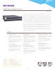
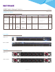
100GE-Enabled Managed Switches Data Sheet
M4500 series
Page 5 of 29