
User Manual


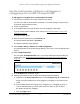

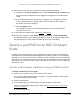

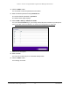
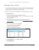
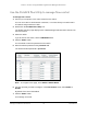
Table Of Contents
- 8-Port or 16-Port 10-Gigabit/Multi-Gigabit Smart Managed Plus Switch with 1 Copper/SFP+ Combo Port
- Contents
- 1 Hardware Setup
- 2 Getting Started
- Configure the switch
- Access the switch using a web browser
- Access the switch with the ProSAFE Plus Utility
- Use the NETGEAR Switch Discovery Tool to access the switch
- Use the NETGEAR Insight App to discover and register the switch
- Change the language of the local browser interface
- Change the password
- Register your product
- 3 Network Settings
- 4 Optimize Performance With Quality of Service
- 5 Use VLANS for Traffic Segmentation
- 6 Manage and Monitor the Switch
- Manage flow control
- Manage the port speed
- Enable loop detection
- Manage Energy Efficient Ethernet and other power saving options
- Upgrade the firmware
- Reboot the switch
- Save the switch configuration
- Restore a saved switch configuration
- Restore factory default settings
- Enable port mirroring
- View switch information
- View the port statistics
- 7 Diagnostics and Troubleshooting
- A Supplemental Information

8-Port or 16-Port 10-Gigabit/Multi-Gigabit Smart Managed Plus Switch
Use VLANS for Traffic Segmentation User Manual65
8. Select the ports that you want to add to the VLAN by doing the following:
a. (Optional) In the Group Operation menu, select Untag All, Tag all, or Remove all.
All ports are either added to the VLAN (tagged or untagged) or removed from the
VLAN.
b. Select individual ports and assign them as tagged (T) or untagged (U) ports or
remove individual ports by selecting the check box under the port numbers.
By default, all ports are untagged.
c. Click the APPLY button.
Your settings are saved. In the VLAN Membership table, the ports display as
members of the VLAN.
9. To select ports for another VLAN, repeat Step 7 and Step 8.
10. To verify your selections, select VLAN > 802.1Q > Advanced > VLAN Configuration.
The Advanced 802.1Q VLAN Status page displays. In the VLAN Identifier Setting table,
the ports display next to the VLAN or VLANS to which they were added.
Specify a port PVID for an 802.1Q-based
VLAN
A default port VLAN ID (PVID) is a VLAN ID tag that the switch assigns to data packets it
receives that are not already addressed (tagged) for a particular VLAN. If you connected a
computer on port 6 and you want it to be a part of VLAN 2, configure port 6 to automatically
add a PVID of 2 to all data received from the computer. This step ensures that the data from
the computer on port 6 can be seen only by other members of VLAN
2. You can assign only
one PVID to a port.
Use the local browser interface to assign a PVID to ports
To assign a PVID to one or more ports:
1. Connect your computer to the same network as the switch.
You can use a WiFi or wired network connection, or connect directly to a switch that is
off-network using an Ethernet cable.
2. Launch a web browser.
3. In the address field of your web browser, enter the IP address of the switch.
If you do not know the IP address of the switch, see Access the switch using a web
browser on page 17.
The login window opens.