
User Manual

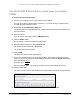
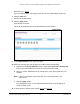
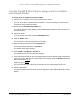
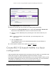

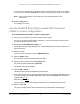
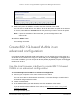

Table Of Contents
- 8-Port or 16-Port 10-Gigabit/Multi-Gigabit Smart Managed Plus Switch with 1 Copper/SFP+ Combo Port
- Contents
- 1 Hardware Setup
- 2 Getting Started
- Configure the switch
- Access the switch using a web browser
- Access the switch with the ProSAFE Plus Utility
- Use the NETGEAR Switch Discovery Tool to access the switch
- Use the NETGEAR Insight App to discover and register the switch
- Change the language of the local browser interface
- Change the password
- Register your product
- 3 Network Settings
- 4 Optimize Performance With Quality of Service
- 5 Use VLANS for Traffic Segmentation
- 6 Manage and Monitor the Switch
- Manage flow control
- Manage the port speed
- Enable loop detection
- Manage Energy Efficient Ethernet and other power saving options
- Upgrade the firmware
- Reboot the switch
- Save the switch configuration
- Restore a saved switch configuration
- Restore factory default settings
- Enable port mirroring
- View switch information
- View the port statistics
- 7 Diagnostics and Troubleshooting
- A Supplemental Information

8-Port or 16-Port 10-Gigabit/Multi-Gigabit Smart Managed Plus Switch
Use VLANS for Traffic Segmentation User Manual58
You can enter a VLAN ID from 1 to 4093. If all the VLANs share an uplink to the Internet
or servers, enter all in the VLAN ID field for the port that you want to use for the uplink.
Note: If ports are members of the same LAG, you must assign them to the
same VLAN.
10. Click the Apply button.
Your settings are saved.
Use the ProSAFE Plus Utility to create 802.1Q-based
VLANs in a basic configuration
To create 802.1Q-based VLANs in a basic configuration:
1. Connect your computer to the same network as the switch.
You can use a WiFi or wired network connection, or connect directly to a switch that is
off-network using an Ethernet cable.
2. Double-click the ProSAFE Plus Utility icon.
The Switch Selection page displays a list of Web Managed switches that it discovers on
the local network.
3. Select the switch.
If you do not see the switch, click the REFRESH button.
4. Click the APPLY button.
You are asked to enter the password for the switch.
5. Enter the switch’s password in the password field.
The switch’s default password is password.
The Switch Status page displays.
6. Select VLAN > 802.1Q.
The Basic 802.1Q VLAN Configuration page displays.
7. If this is the first time that you are accessing the Basic 802.1Q VLAN Configuration page or
if you are changing the VLAN assignment method, select the Enable radio button and
continue with
Step 8.
Otherwise, go to Step 9.
A pop-up window opens, informing you that the current VLAN settings will be lost.
8. Click the Yes button.
The pop-up window closes and the Basic 802.1Q VLAN Identifier table displays.