
User Manual
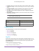
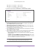

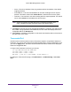
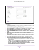
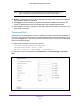
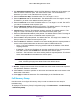
Table Of Contents
- M6100 Web Management User Guide
- Contents
- 1. Getting Started
- 2. Configuring System Information
- 3. Configuring Switching Information
- 4. Routing
- 5. Configuring Quality of Service
- 6. Managing Device Security
- 7. Monitoring the System
- 8. Maintenance
- 9. Help
- A. Default Settings
- B. Configuration Examples
- C. Notification of Compliance

Maintenance
538
M6100 Web Management User Guide
1. Use IPv6 Address/Hostname to enter the IPv6 address or Hostname of the station you
want the switch to discover path. The initial value is blank. The IPv6 Address or
Hostname you enter is not retained across a power cycle.
2. Enter the Probes Per Hop. The default value is 3. The range is 1 to 10.
3. Enter the Maximum TTL for the destination. The default value is 30. The range is 1 to 255.
The MaxTTL you enter is not retained across a power cycle.
4. Enter the Initial TTL to be used. The default value is 1. The range is 1 to 255. The InitTTL
you enter is not retained across a power cycle.
5. Enter the Maximum Failures allowed in the session. The default value is 5. The range is 1
to 255. The MaxFail you enter is not retained across a power cycle.
6. Interval (secs) - Enter the Time between probes in seconds. The default value is 3. The
range is 1 to 60. The Interval you enter is not retained across a power cycle.
7. Enter the UDP Destination Port in probe packets. The default value is 33434. The range is
1- 65535. The port you enter is not retained across a power cycle.
8. Enter the Size of the probe packets. The default value is 0. The range is 0 to 39936. The
Size you enter is not retained across a power cycle.
9. Enter the Source IP address or interface to use when sending the echo request packets. If
source is not required, select None as the source option. Possible values are:
• None — The source address of the ping packet would be the address of the default
outgoing interface.
• IP Address — The source IP address to use when sending the Echo request packets.
This field is shown when IP Address is selected as the source option.
• Interface — The interface to use when sending the Echo request packets. This field is
shown when Interface is selected as the source option.
Note: Values configured in the fields above are not saved to the switch. As a
result, refreshing the page sets these fields to the default values.
10. Results - Displays the traceroute IPv6 result after the switch sends a traceroute request to
the specified IP address or hostname.
11. Click Cancel to cancel the operation on the screen and reset the data on the screen to the
latest value of the switch.
12. Click Apply to initiate the traceroute. The results display in the TraceRoute area.
Full Memory Dump
Use this screen to configure full memory dump in order to retrieve the core dump for
troubleshooting.
To display the Full Memory Dump Configuration page, click Maintenance Troubleshooting
Full Memory Dump.