
User Manual
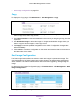
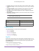
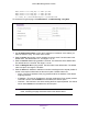
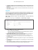

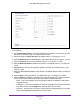
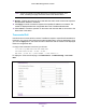


Table Of Contents
- M6100 Web Management User Guide
- Contents
- 1. Getting Started
- 2. Configuring System Information
- 3. Configuring Switching Information
- 4. Routing
- 5. Configuring Quality of Service
- 6. Managing Device Security
- 7. Monitoring the System
- 8. Maintenance
- 9. Help
- A. Default Settings
- B. Configuration Examples
- C. Notification of Compliance

Maintenance
532
M6100 Web Management User Guide
1. Use Unit to select the unit whose code image you want to activate, update, or delete.
2. Use Next
Active Image to make the selected image the next active image for subsequent
reboots.
3. Use Image Description to specify the description for the image that you have selected.
4. Click Delete to delete the selected image from permanent storage on the switch.
5. Click Apply to send the updated configuration to the switch. Configuration changes take
ef
fect immediately.
6. Click Cancel to cancel the configuration on the screen and reset the data on the screen to
the latest value of the switch.
Field Description
Image Name This displays the image name for the selected unit.
Active Image Displays the current active image of the selected
unit.
Version Displays the version of the image1 code file.
Note: After activating an image, you must perform a system reset of the
switch in order to run the new code.
Troubleshooting
The Troubleshooting menu contains links to the following options:
• Ping IPv4 on page 532
• Ping IPv6 on page 534
• Traceroute IPv4 on page 535
• Traceroute IPv6 on page 537
• Full Memory Dump on page 538
Ping IPv4
Use this screen to tell the switch to send a Ping request to a specified IP address. You can
use this to check whether the switch can communicate with a particular IP station. Once you
click the Apply button, the switch will send a specified number of ping requests and the
results will be displayed.
If a reply to the ping is not received, you will see:
Tx = Count, Rx = 0 Min/Max/Avg RTT = 0/0/0 msec
If a reply to the ping is received, you will see: