
User Manual
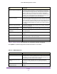
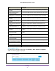
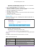
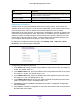

Table Of Contents
- M6100 Web Management User Guide
- Contents
- 1. Getting Started
- 2. Configuring System Information
- 3. Configuring Switching Information
- 4. Routing
- 5. Configuring Quality of Service
- 6. Managing Device Security
- 7. Monitoring the System
- 8. Maintenance
- 9. Help
- A. Default Settings
- B. Configuration Examples
- C. Notification of Compliance

Routing
248
M6100 Web Management User Guide
Table 94, IPv6 Advanced Route Preferences describes the non-configurable data that is
displayed.
Table 94. IPv6 Advanced Route Preferences
Field Description
Local The local preference.
IPv6 Tunnel Configuration
Use this screen to create, configure, and delete tunnels.
To display the IPv6 configure page, click Routing
IPv6 Advanced Tunnel
Configuration. The following page is displayed.
Configure IPv6 Tunnel.
1. In the T
unnel ID field, select from the list of available tunnel IDs.
2. Select the tunnel Mode from the list of supported modes:
• 6-in-4-configured
• 6-to-4
3. Select the IPv6 Mode from the list. Enable IPv6 on this interface using the IPv6 address.
This option is only configurable prior to specifying an explicit IPv6 address.
4. From the IPv6 Unreachables list, select to Enable or Disable the mode of sending ICMPv6
Destination Unreachables on this interface. If Disabled then this interface will not send
ICMPv6 Destination Unreachables. By default IPv6 Destination Unreachables mode is
enable.
5. In the IPv6 Address/Prefix
Length field, enter a configured IPv6 address for the selected
interface. The address must be entered in the format prefix/length.
6. From the EUI64 list, select to Enable or Disable the 64-bit extended unique identifier
(EUI-64). For 6to4 tunnels, configure the ipv6 address with first 48-bits in the format
2002:tunnel-source-ipv4-address::/48.
7. Specify the desired Source Address for this tunnel.
This value must be entered in dotted
decimal notation.
8. Select the Source Interface for this tunnel.
The address associated with the selected
interface will be used as the source address.
9. Enter the Destination Address for this tunnel in dotted decimal notation.
10. Click Add to add a new tunnel configuration.
11. Click Apply to send the updated configuration to the switch. Configuration changes take
ef
fect immediately.