
User Manual

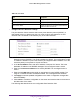
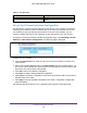


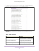

Table Of Contents
- M6100 Web Management User Guide
- Contents
- 1. Getting Started
- 2. Configuring System Information
- 3. Configuring Switching Information
- 4. Routing
- 5. Configuring Quality of Service
- 6. Managing Device Security
- 7. Monitoring the System
- 8. Maintenance
- 9. Help
- A. Default Settings
- B. Configuration Examples
- C. Notification of Compliance

Configuring Switching Information
205
M6100 Web Management User Guide
Table 80. VPC Interface Configuration
Field Description
State The VPC interface’s operational mode, which is one
of the following:
• Disabled — VPC functionality is operationally
disabled on the VPC interface.
• W
ait — The port channel is waiting for VPC
functionality to be enabled on a port channel on
the peer device.
• Error — VPC functionality is enabled on a port
channel on both peer devices, but not all entry
criteria are met for the port channel to be
operational. For example, if the combined
number of member ports for the VPC interface is
more than the maximum allowed, then the state
is set to Error on both devices.
• Active — VPC functionality is enabled on a port
channel on both peer devices, and all entry
criteria are satisfied.
The VPC interface is
operationally enabled, and traffic is allowed to
flow through the VPC member ports.
• Inactive — The links connected to the VPC
member ports are down, but the VPC interface
on the peer remains active.
Virtual Port Channel Interface Details
To display the Virtual Port Channel Interface Details page, click Switching > MLAG >
Advanced > VPC Interface Details. The following page is displayed.
1. Select an interface from the list of LAG Interfaces which are configured as VPC
interfaces.
2. The following table describes the non-configurable VPC details that are displayed.