
User Manual


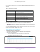
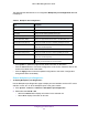

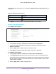
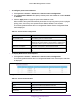


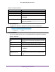
Table Of Contents
- M6100 Web Management User Guide
- Contents
- 1. Getting Started
- 2. Configuring System Information
- 3. Configuring Switching Information
- 4. Routing
- 5. Configuring Quality of Service
- 6. Managing Device Security
- 7. Monitoring the System
- 8. Maintenance
- 9. Help
- A. Default Settings
- B. Configuration Examples
- C. Notification of Compliance

Configuring System Information
90
M6100 Web Management User Guide
Table 47. EPS Power Modules
Field Description
Slot EPS power module number counted from left to right.
Type EPS power module type. Valid value is Removable.
State EPS Power module state. Possible states are:
• Operational
• Not Present
AC EPS power module input voltage category in volts. Possible values
are 1
10V, 220V and N/A. N/A specifies that power source input
voltage cannot be obtained.
To display EPS ports:
1. Click System > Chassis >
Advanced > Chassis Power Configuration.
Figure 21. EPS Ports
The following table describes the non configurable EPS Ports data that is displayed.
Table 48. EPS Ports
Field Description
Ports EPS port number counted from left to right while facing rear side of
the chassis.
State EPS port state. Possible state is Not present or Operational.
Sharing Status EPS power sharing status.
Device Type Device type. Possible values are:
• RPS4000v1
• RPS4000v2
• Unknown
EPS/RPS Port Group Group of EPS slots connected to this port. Possible values are:
• 1,2
• 3,4